Classic Management of Raster Images (AutoCAD)
| Command: | Classic Management |
| Menu path: | Basemaps > Classic Management |
| Icon: | 
 |
| Functional description: | In AutoCAD 2006
command opens (AutoCAD) window Image Manager which shows loaded raster basemaps and allows their handling and loading of new ones. In AutoCAD 2012 command opens (AutoCAD) window External Reference which shows loaded raster and vector basemaps and allows their handling and loading of new ones. |
By opening Image Manager window (i.e. External Reference if it is ACAD 2012), we can
handle already loaded basemaps, as well as manually load new raster images
or change paths to those already loaded. In this manner, it is possible
to carry out loading of other significant raster images you’d like to
show on the drawing.
Understanding the work with raster images
In order to use Image Manager window and
all the commands in it,
you must first understand how AutoCAD works with raster images.
Raster image referencing
Raster images can be located within DWG files only by means of referencing.
This means that the raster image itself never becomes a part of DWG file
(as is the case with Microsoft Word, for instance).
Inside the DWG file there is only a frame within which the raster image
is displayed.
The frame is automatically generated when we insert the raster image into
the drawing.
This frame is a vector object and it is the one that contains the reference
leading to the raster image file.
The reference is actually an address where the raster image file is located,
i.e. address where AutoCAD expects the raster image file to be.
If the raster image, which has already been inserted into the drawing,
is not located at the given address,
AutoCAD will search for the raster image file with the same name inside
the folder where the DWG file itself is located.
If it does not find it there either, it will show an empty frame with a
written reference, i.e. address where AutoCAD expects the raster image
file which is to be shown.
The very raster image file can be located anywhere on the disc, but internet as well (in that case its reference would be the internet address of the raster image file).
While working with TeleCAD-GIS, we’re only interested in the case when a raster image is on the hard disc, in which case we have two options:
- Raster image file address is given as absolute path.
- Raster image file address is given as relative path.
Let’s assume we have a folder “Test
project1" containing DWG file and folder "Basemaps",
with raster image basemaps.
All of it is located somewhere on the hard disc of our computer. Let us
assume that the basemaps are already inserted into the DWG drawing.
Absolute path
When the raster image file address is given as an absolute path, it
looks like this:
E:\TCG Project Folder\Test
1\Test Project1\Basemaps\dl026.tif (where „dl026.tif” is
the name of the raster image itself).
The absolute path is the full path to the file on the hard disc.
The consequence of setting this type of path is as follows:
If we move “Test project1” folder along with all its content to another
computer, AutoCAD will try to find the raster image on the computer’s
address. It is almost certain that the computer will not contain folders
with the same name and arrangement. When AutoCAD opens the transferred
DWG file, it will not be able to display raster image, only the empty
frame (as described earlier).
Relative path
When the raster image file address is given as a relative path, it looks
like this:
.\Basemaps\dl026.tif
(where "dl026.tif" is the raster image name).
This address means that the raster image file is located in the "Basemaps"
folder,
and the "Basemaps" folder is located in the same folder as the
DWG file
( „ .\ ” denotes a folder
where the DWG file is located, and the path search starts from this folder,
in this case “Test Project1” folder).
The consequence of setting this type of path is as follows:
If we move “Test project1” folder along with all its content to another
computer, AutoCAD will try to find the “Basemaps” folder within the folder
where the very DWG file is located (“Test Project1”). Since it has all
been moved together, the raster image files will be exactly where AutoCAD
expects them to be. “Test Project1” folder’s transfer is hereby enabled
without interruption of the raster image file reference.
Raster image instances
Since the raster image is inserted into the DWG drawing as a reference,
what the user can see in the drawing is the raster image instance.
(Raster image frame is the instance).
There does not have to be only one raster image instance, there can be
more of them and they can be differently rotated, reduced, increased,
etc.
(Raster image instances are generated by copying the first instance or
reinserting of the raster image which is already in the drawing.)
All these instances display the same raster (they are referenced towards
the same raster image file).
In this manner, the size of the DWG file can be insignificantly enlarged
regardless of how many times the raster image has been copied.
What affects the size of the file are the frames within which raster images
are displayed.
Window: Image Manager (AutoCAD 2006)
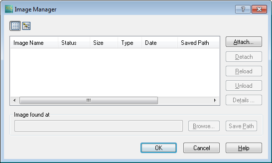
Figure 1
The Image Manager window contains the following elements:
Icons
Use them to determine raster image display mode in the list:
 List Display (raster image
display in the list)
List Display (raster image
display in the list) Tree Display (raster image
display in the tree)
Tree Display (raster image
display in the tree)
List
It contains the following information about the raster image:
- Image Name (name of the image/ raster image)
- Status:
1. Loaded-if the raster image is found on the given path, the status shall be “Loaded”
2. Not found-If the raster image is not found on the path, the status will be "Not Found"
3. Unload - The raster image is found, but it will not get loaded (this happens at the request of users - Unload button) - Size (file size)
- Type (file type)
- Date (the date and time when the file was last saved)
- Saved Path (i.e. the address where AutoCAD expects the raster image file to be)
Buttons:
- Attach
This command will attach the raster image file to the DWG file (create a reference). - Detach
This command will detach the raster image file (delete the reference) - Reload
The command will reload the raster image file. - Unload
The raster image will not be loaded if there is a reference towards it. - Details
It opens a window with detailed data about the raster image file.
Image found at
It displays the path where the raster image file was found:
- The entry box with displayed path where the raster image file was found.
- Browse
It opens the browser used to find the raster image file on the hard disc.
(Most commonly used in case the raster image file is not on the expected path, so it needs to be found manually) - Save path
If the user changes the path to the raster image file, clicking this button will save the new path, i.e. new reference.
Buttons:
- OK - it will perform an action with the raster image as marked in the status box (load, unload, detach...)
- Cancel - quit all the actions, the window is closed
- Help - opens AutoCAD help regarding operations with Image Manager window.
All the options of raster image handling available by using Image Manager window commands go beyond the limits of this text and depend mostly on the resourcefulness of users. Additional clarifications regarding this window can be viewed by clicking Help button on this window (explanations are in English). On this occasion only the process of raster image insertion into a drawing will be explained.
Process of raster image insertion into a drawing (AutoCAD 2006)
From the main menu Basemaps > Classic Management
command is run
Image Manager window appears (Figure 2).
Figure 2
By clicking Attach, the browser is opened
(Figure 3) and used to find the raster image file which should be inserted
(attached) into the drawing.
Once the file is found, it should be marked and Open
button clicked.
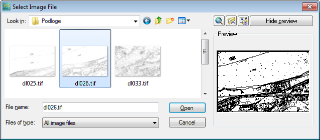
Figure 3
After clicking Open, Image window opens.
Image window can be used to set the definition
method of reference towards the raster image file
(absolute or relative path; Path type: Full path = absolute path, Relative
path).
If Insertion Point, Scale and Rotation
ticking boxes are left as they are in Figure 4,
the position and size of the raster image can be defined in the drawing
itself.
The program will not offer rotation of the inserted raster image.
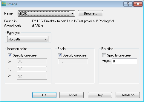
Figure 4
Clicking OK closes Image window, after which
the Site Plan Drawing can be viewed.
By clicking on the drawing area, set the raster image insertion point on
the drawing, and
by moving the mouse up to the point, set the raster image display size
(scale).
While the mouse is moving, the frame showing the raster image display size
is being shown.
When the size is satisfactory, click again and the raster image is inserted
into the drawing.
| Warning: |
The raster image inserted like this is not georeferenced, nor is its scale proper, so use this approach only if your drawing needs a raster image where these data are irrelevant. (For instance, a scanned manhole diagram used only to see the allocation of elements on manhole sides.) or If it is about a basemap which
cannot be calibrated by Calibrate
Raster Image command, such a basemap can be inserted into
the drawing in this manner, but it should be placed as precisely
as possible by using AutoCAD command AL (ALIGN) |
Window: External References (AutoCAD 2012)
Figure 5 - External References window when the "Details" are not displayed. |
Figure
6 - External References window when
the "Details" are not displayed. |
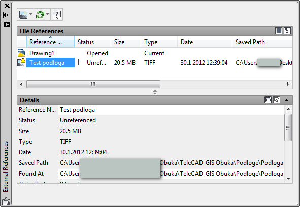
External References window contains the following
elements:
- The main tool (icon) pallet
- “File References”
- "Details"
The main tool (icon) pallet
 Attach
DWG
Attach
DWG
This is the initially displayed command. Next to the very icon there is
a small black triangle.
Clicking it opens a drop-down menu which also displays other commands of
this group which serve to insert various objects into a DWG drawing:
- Attach DWG
This command will attach the external DWG file to the active DWG file (create a reference).
(Attach Drawing command is derived from this command and works in a similar manner.)
 Attach Image
This command will attach the raster image file to the DWG file (create a reference).
It is actually a command used to load raster image basemaps.
(After the first use the command (icon) will replace the initial one up until the drawing is closed.)
- Attach DWF
- Attach DGN
- Attach PDF
 Refresh

- Refresh - Refresh window display
- Reload All References - The
command will reload all the referenced files.
 Help
- (Open AutoCAD help referring to this window (in English))
Help
- (Open AutoCAD help referring to this window (in English))
“File References”
It contains the following information about the raster image (and all the other file types, but the greatest attention will be paid to raster images):
- Reference Name
- Status:
1. Loaded - if the raster image is found on the given path, the status will be “Loaded”
2. Not found - If the raster image is not found on the path, the status will be "Not Found"
3. Unload - The raster image is found, but it will not get loaded (this happens at the request of users - commands: Unload, (from the context menu, see below)) - Size (file size)
- Type (file type)
- Date (the date and time when the file was last saved)
- Saved Path (i.e. the address where AutoCAD expects the raster image file to be)
"File references" icons
Use them to determine raster image display mode in the list:
 List View (display
of referenced files in the form of a list)
List View (display
of referenced files in the form of a list) Tree View (display
of referenced files in the form of a tree)
Tree View (display
of referenced files in the form of a tree)
"File references" context menu:
(The context menu opens by right-clicking on a list item).
- Attach
This command will attach the raster image file to the DWG file (create a reference). - Unload
The raster image will not be loaded if there is a reference towards it. - Reload
The command will reload the raster image file. - Detach
This command will detach the raster image file (delete the reference)
"Details"
It is opened by clicking on a little black triangle at the end of the
gray bar named “Details”. It shows various details relating to the item
selected in “File References" (above).
Most of the items are informative and clear per se, so they will not undergo
any particular explanations.
Pay attention to two items:
- Saved Path - (absolute or relative) saved path, i.e. address where AutoCAD expects to find the referenced raster image (or external file).
- Found At - path where the
raster image was actually found and really found (see Understanding
of working with raster images). At the right end of the field,
there is an icon (
 altalt)
which opens the browser used to find the raster image (for instance,
if the raster image is not on the expected path). The new path will
be saved automatically.
altalt)
which opens the browser used to find the raster image (for instance,
if the raster image is not on the expected path). The new path will
be saved automatically.
All the options of raster image handling available by using External References window commands go beyond the limits of this text and depend mostly on the resourcefulness of users. Additional clarifications regarding this window can be viewed by clicking Help icon on this window (explanations are in English). On this occasion only the process of raster image insertion into a drawing will be explained.
Process of raster image insertion into a drawing (AutoCAD 2012)
From the main menu Basemaps > Classic Management
command is run
External References window opens (Figure 7).
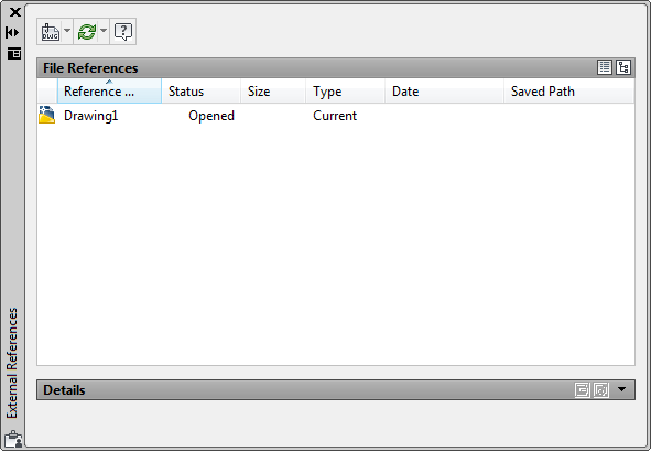
Figure 7
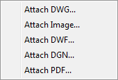
By clicking on the little black arrow next to Attach
DWG icon, a drop-down menu opens, from where Attach
Image command is selected (Figure 8).
The command opens the browser used to find the raster image file to be
inserted (attached) to the drawing.
Once the file is found, it should be marked and Open
button clicked (Figure 8).
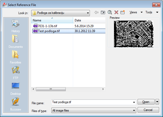
Figure 8
After that, Attach Image window opens.
Attach Image window can be used to set the
definition method of reference towards the raster image file
(absolute or relative path; Path type: Full path = absolute path, Relative
path).
If Insertion Point, Scale and Rotation
ticking boxes are left as they are in Figure 9,
the position and size of the raster image can be defined in the drawing
itself.
In this case, the program will not offer rotation of the inserted raster
image.
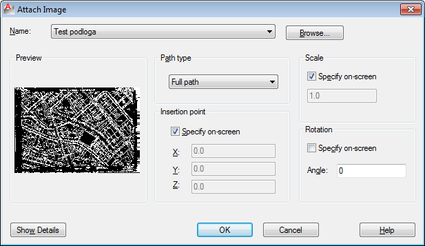
Figure 9
Clicking OK closes Attach Image window,
after which the Site Plan Drawing can be viewed.
By clicking on the drawing area, set the raster image insertion point on
the drawing, and
by moving the mouse from the point, set the raster image display size (scale).
While the mouse is moving, the frame showing the raster image display size
is being shown.
When the size is satisfactory, click again and the raster image is inserted
into the drawing.
| Warning: |
The raster image inserted like this is not georeferenced, nor is its scale proper, so use this approach only if your drawing needs a raster image where these data are irrelevant. (For instance, a scanned manhole diagram used only to see the allocation of elements on manhole sides.) or If it is about a basemap which
cannot be calibrated by Calibrate
Raster Image command, such a basemap can be inserted into
the drawing in this manner, but it should be placed as precisely
as possible by using AutoCAD command AL (ALIGN) |