MMF Cable (designed)
| Command: |
MMF Cable (designed) |
| Menu path: |
Fiber Optics > MMF Cable (designed) |
| Icon: |

 |
| Functional description: |
Laying MMF cable with the property
Cable Status - Designed. |
| |
MMF Cable (designed) command lays MMF cable with predefined properties.
Figure 1 shows MMF cable display in the site plan drawing.
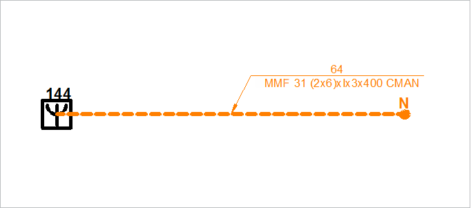
Figure 1
By laying in this way, you’ll get the cable with the following properties:
Properties
Optical Cable:
- Cable type - Custom
- Fiber type - Multi-mode
- Coating type - (default coating type, defined in the system
settings)
- Reinforcement type - (default reinforcement type, defined
in the system settings)
- Number of buffer tubes -
(zero)
- Number of fibers - (zero)
- Waveband - (default waveband, defined in the system
settings)
- Attenuation (db/km) - (default attenuation, defined in
the system settings)
- Bandwidth (MHz/km) - (default bandwidth, defined in the
system settings)
- Cable status - Designed
- Pathway type - Underground
- Year built - (current year is offered)
Structural features:
- With fibers in tubes - (yes/no - defined in the system
settings)
- Slotted core cable - (yes/no - defined in the system settings)
- Filled cable - (yes/no - defined in the system settings)
- With aramid fibers - (yes/no - defined in
the system settings)
- Without metal elements - (yes/no - defined in the system
settings)
FO cable length:
- Trench length (m) - length obtained from the drawing
- Sinuosity (%) - (default sinuosity, defined in the system
settings)
- Sinuosity (m) - automatically calculated on
the basis of the previous item
- Slack loop length (m) - the sum of all cable's slack
loop lengths
- Length (m) - length calculated based on the previous
items related to length (displayed on the cable label, if
the fixed length is not entered)
- Fixed length - 0.0 (as-built length)(entered by the user
based on the on-site data and displayed on the cable label,
if entered)
- Optical length - 0.0 (entered by the user based on the
on-site data (OTDR measures))
TCG Global Properties:
- TCG Object Identifier - (identification number)
- Note - (write an arbitrary note that refers to the selected
FO cable)
- Owner - (infrastructure owner)
- User - (infrastructure user)
|
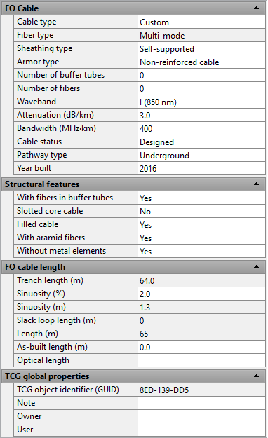
Figure 2 |
These properties can be changed through the Properties
window (Figure 2).
Procedure of laying cables
The laying procedure is the same for all cables.
The only difference is in the properties assigned to the cable after drawing.
The procedure is described on Laying FO
Cable page.
Laying FO cables is possible only between the nodal elements of fiber
optic network:
- Splice Point (Optics)
- Optical Distribution Frame (ODF)
- OTB (Optical Termination Box)
- Patch Panel
- IPAN
- FO router
- FO splitter
- ...
| Clarification: |
If during the cable laying, to the program’s request to
select the nodal element you click on an element that doesn’t
belong to FO network (e.g. manhole or copper DT), the program
will simply ignore it until you select one of the abovementioned
FO elements. |
|