Vezivanje na šemi
Since TeleCAD-GIS 2018 version it is possible to perform fiber splicing
and connecting on the schematic diagram itself.
So, now we can connect or terminate fibers in a nodal element without opening
its detailed schematic diagram (view).
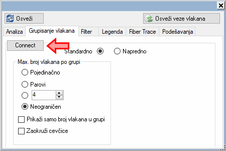
Process is initiated by switching to "fiber splicing mode"
while we are on the fiber schematic
diagram.
We do that by clicking on the Connect button
which is located on the Fibers grouping tab
of the schematic diagram's floating window (image below).
(Press Esc on your keyboard when you want
to leave "fiber splicing mode".)
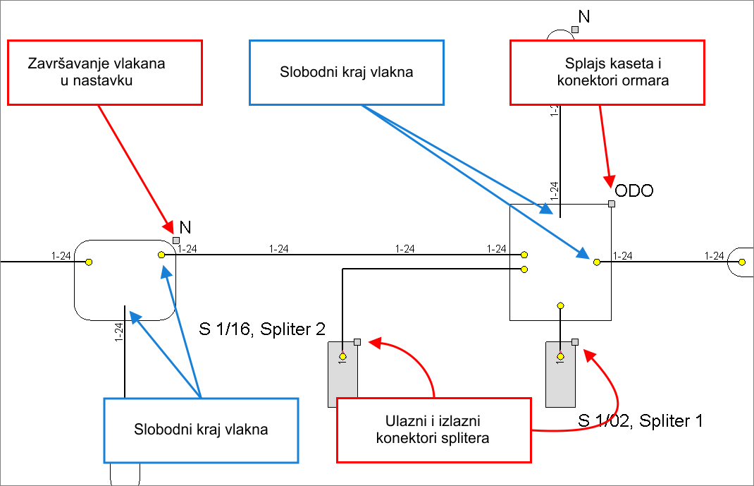
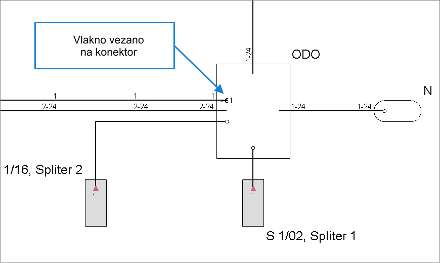
Once we are in the "fiber splicing mode", nodal elements shall display additional graphical symbols (small circles and squares) which we shall use to indicate what we want to connect.
Below image shows the look of free end of the fiber ready to be connected:
- if the fiber end has no symbol it just means that it is not connected on the opposite end
- yellow circle means that the fiber is connected on the opposite end
In both cases it is possible to connect/splice these fibers within given
nodal element (in this case FDB) - to other fibers, devices (e.g. splitters)
or they can be terminated in a splice-box.
Grey squares enable connecting to a patch panel connectors and a splice-box
(in case of FDB) or to a incoming and outgoing ports of a device (e.g.
splitter) within that FDB.
| Note: |
Devices (splitters) SHALL NOT BE VISIBLE until we connect some fibers to them. We advice you to connect some patch cable to a splitter in a
standard way (by opening detailed schematic diagram of a FDB)
to make splitters visible. |
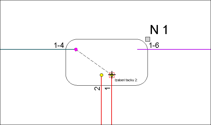
While we are in the "fiber splicing mode", cursor changes
to cross-mark with circle (image below).
Program expects user to indicate ends of those polylines whose fibers it
wants to connect and which are within a same nodal element (in our example
- splice case).
(Keep in mind that polylines can represent one or more grouped fibers depending
on a settings on a Fibers grouping tab.
Also, it is possible to splice connect fibers to connectors and splice-box.
We shall talk more about this later in the text.)
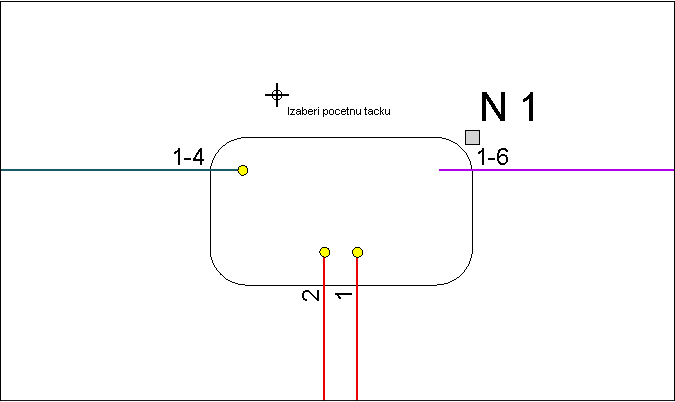
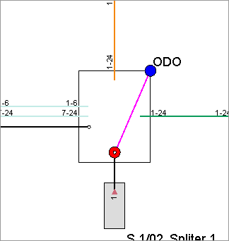
First we click on the end of a polyline that represents a fiber (or fibers)...
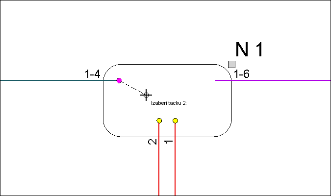
... a zatim i na kraj druge polilinije unutar nastavka.
... than on the end of another polyline within the splice case.
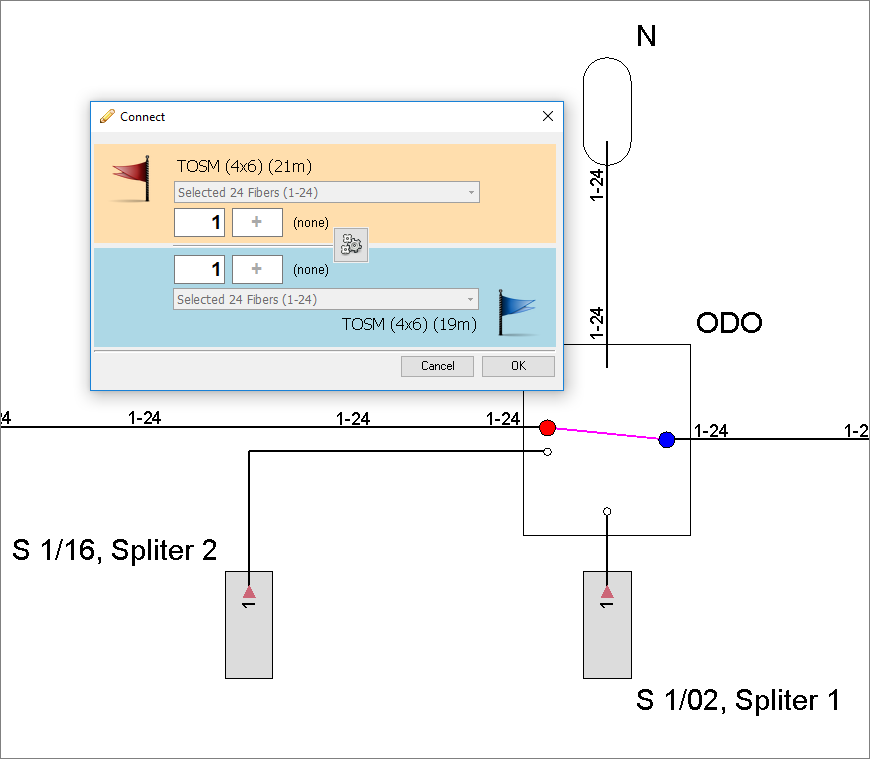
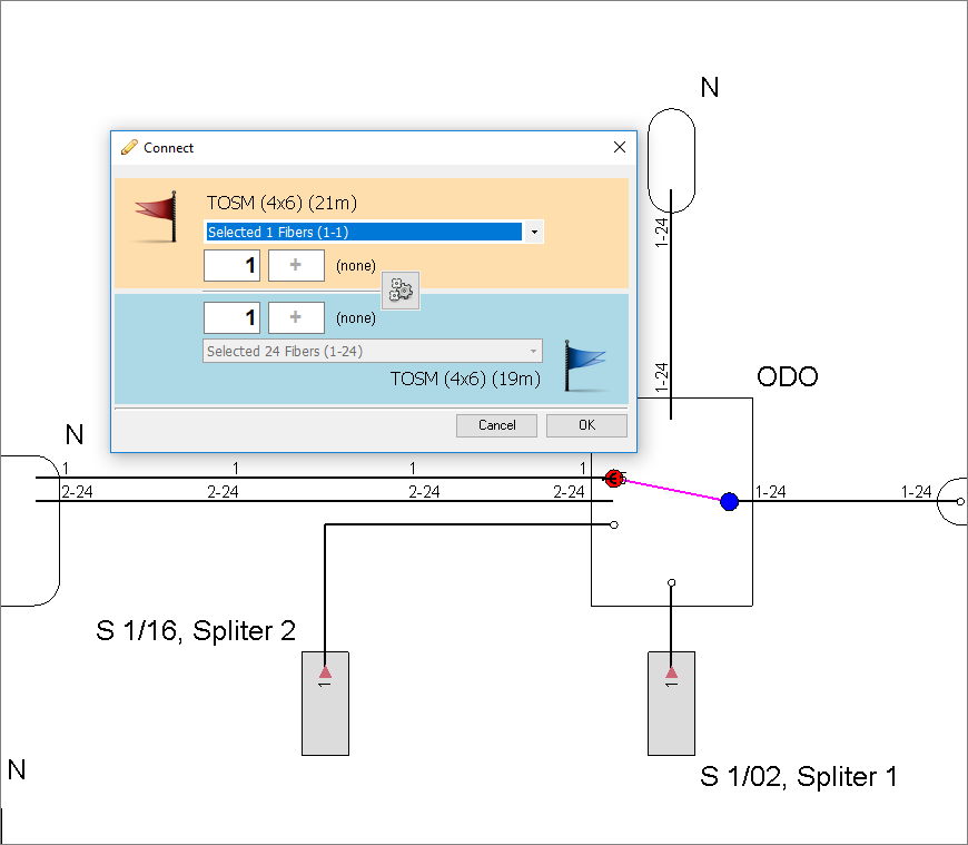
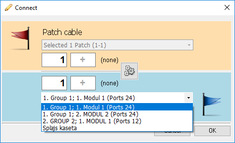
This shall open the Connect
window that displays available fibers.
Fibers that we have selected first are marked with red
dot on the schematic diagram and with a red flag on the Connect
window.
Fibers that we have selected second are marked with blue
dot on the schematic diagram and with a blue flag on the Connect window.
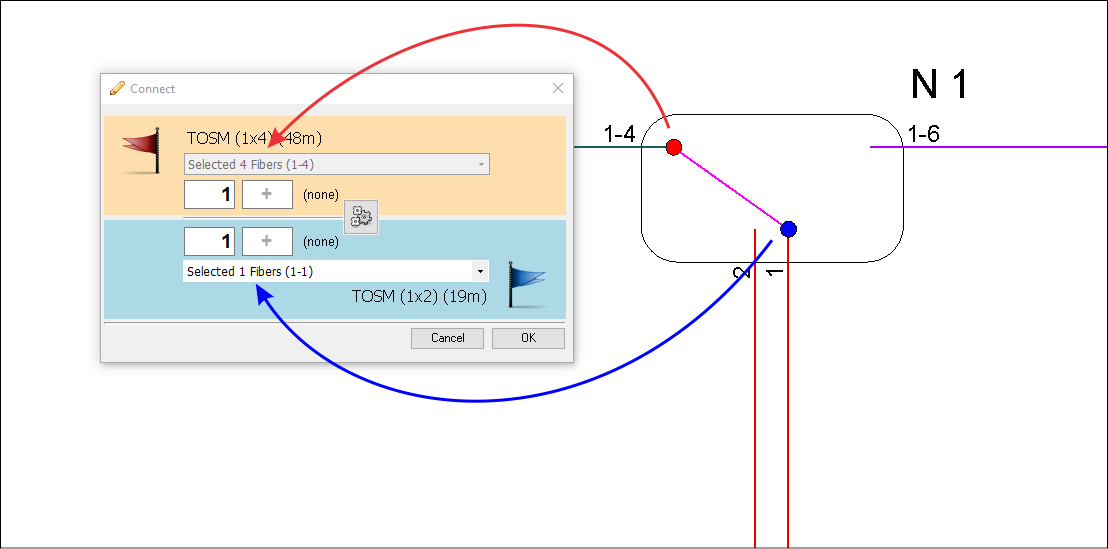
The Connect window contains elements available
for splicing.
In the given example in both cases we are dealing with fibers but keep
in mind that those can also be connectors or splice-box (we shall talk
more about this later on this page).
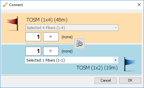
U kućice crvene, a i u kućice plave zastavice unosimo vlakna koja želimo
vezati.
We use input boxes of "red" and "blue" element to indicate
fibers that we want to connect.
Fibers are inserted in a "from - to" format.
In our example we want to connect fiber 1 of the TOSM (1x4)(48m) cable
with the fiber 1 of the TOSM (1x2)(19m) cable.
In this case it is not necessary to fill in "to" input box.
Program will simply assume tat we want to connect a single fiber if we
leave input box "to" - empty.
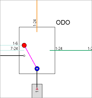
Click OK to finish splicing.
The program shall prompt us to confirm.
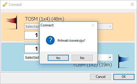
Click Yes to finish the process.
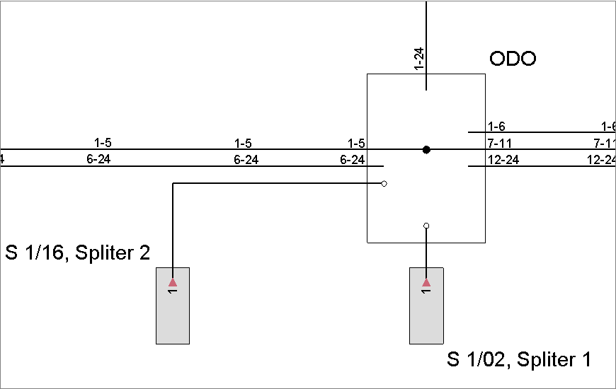
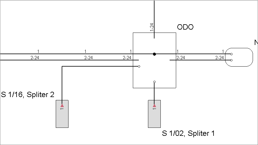
After this the fibers are spliced which can bee immediately seen on the
fiber schematic diagram (image below).
And that's it, as far as the splicing technique is considered.
Let us now see, in more details, what more can we do in this way and how else to use Connect window.
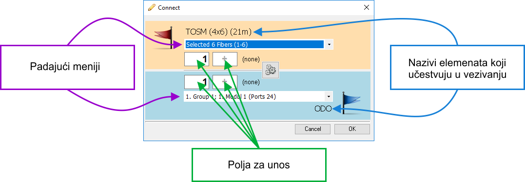
„Connect” window
The Connect window is divided into two areas.
Red flag area and blue
flag area.
Red flag area refers to elements that we have selected first on the schematic
diagram.
Blue flag area refers to elements that we have selected second on the schematic
diagram.
Both areas contain drop down lists and input fields. Between areas there
is the "calculate" button -  .
.
Drop down lists enable change or expansion of initially offered group of
elements (fibers and/or connectors) intended for splicing.
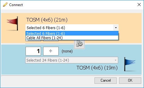
In case of cables, if we haven't selected an entire cable, initially only a group of fibers selected on the schematic diagram shall be at our disposal. We can only use for splicing fibers selected on the drop-down list. In our case those are:
|
|
By selecting „Cable All Fibers” item from the drop-down list we can put at our disposal all fibers of the red area cable.
|
|

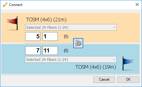
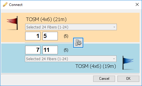
Input fields are used to accurately define elements (fibers/connectors)
that actually participate in splicing.
Input needs to be in "from -to" format.
For example: We need to splice fibers 1- 5 to fibers 7-11. All four input fields can be filled manually. The program shall calculate required range and fill in remaining input field.
|
|
In previous case we have spliced fibers in a following manner: fibers 1-5 to fibers 7-11. If we wanted to we could have spliced them in reverse order: fibers 5-1 to fibers 7-11 In this case we would fill in the input fields like on the image on the right.
|
|
Finally, Connect window has two buttons:
- Cancel - cancels the splicing process
- OK - proceed with splicing as defined on the window
What all can be spliced
Fiber to fiber splicing (I)
Fiber splicing process starts by marking two free polyline ends that represent fibers. After this, Connect window opens that allows splicing of selected fibers (image below).
On the Connect window, fill in the input fields to indicate what fibers are to be connected.
By clicking on the OK button we confirm
and thus finish splicing process.
Fibers are now represented as shown on the image below.
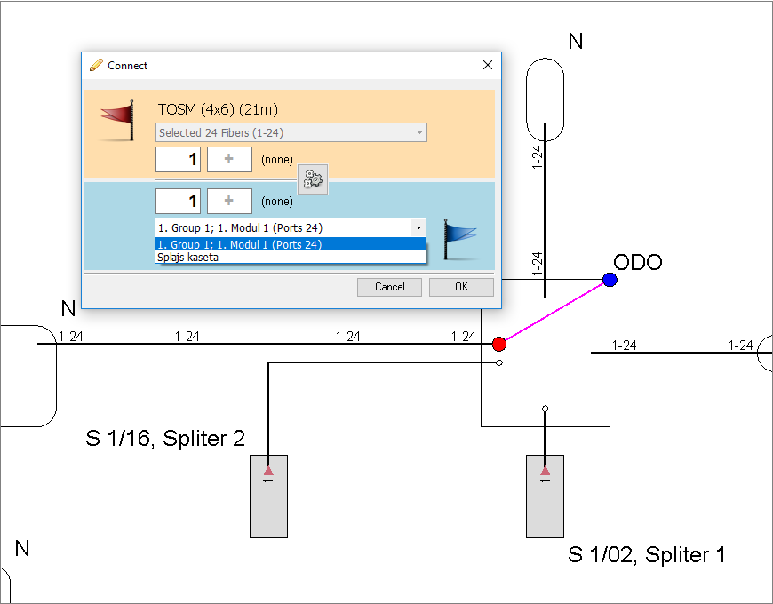
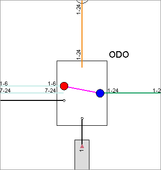
Fiber to connector splicing
In the next example, we have selected fibers on one end (red
circle) and grey square (overlapped by blue
circle) that represents patch pannel and splice box of FDB on the
other end.
This shall open the Connect window. In the
blue area (that refers to FDB) there is a drop-down list that offers selection
of a module or a splice box.
User can choose what to connect fibers to.
After the selection, input fields of the red flag area need to be filled
in with fibers that we want to connect and in the blue flag area we need
to input connectors that are to be used in connection.
(Note: When we are terminating fibers in the splice-box - input fields
of the splice-box will be disabled because splices are not numerated (unlike
connectors) and there fore not required. It is sufficient to say what
fibers are to be terminated.)
After terminating a fiber to a connector, end of the fiber shall display a connector symbol as well as number of connector that it is now connected to
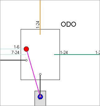
Now, if we would connect already terminated fiber to a free fiber (image below)...
We would, again, have two directly spliced fibers (same as when we were
connecting free fibers).
So, the program has disconnected the fiber from the connector and directly
spliced it to a free fiber.
The same would happen if we would connect two fibers that were previously
been terminated on connectors.
There is no way to make a connection with patch cable directly on the schematic
diagram in "fiber splicing mode".
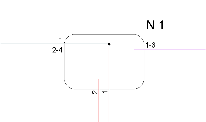
Fiber to fiber II
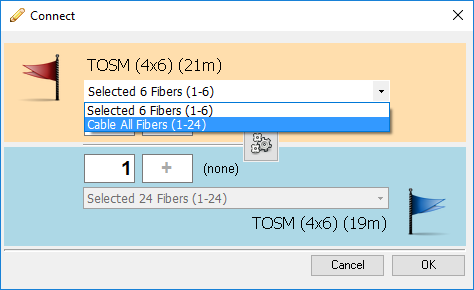
Left cable is divided into two fiber groups. We have selected for splicing the group with 6 fibers (red). All fibers of the right cable are represented with only one
polyline. |
|
Drop-down list of the red flag area initially displays only "6 fibers" item. Input fields of the red flag area will only accept fibers ranging from 1 to 6. It is assumed that this is exactly what you want since these are the fibers you have selected on the schematic diagram. However, you are given an oportunity to...
|
|
... expand selection to all cable fibers by selacting „Cable All Fibers” item from the drop-down list. |
|
Now, input fields will accept any value from 1 to 24 which is the full capacity of this particular cable.
|
|

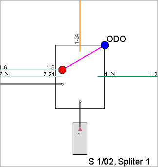
Fiber to a patch panel or a splice-box
The schematic diagram on the right displays group of fibers (1-6) and a grey square that enables connecting to a FDB connectors or its splice-box. Note: Square is not visible because it is covered with blue circle.
|
|
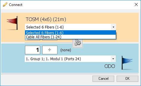
Since the cable is selected first it appears on the red flag area. Initially fibers 1-6 are available for splicing but it can be expanded to all cable fibers.
|
|
FDB is selected second in line therefore it appears on the blue flag area. Initially, its first connectors module is selected but that can be changed to any module or to its splice-box.
|
|
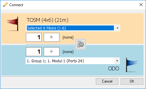
After making a selection we are ready to insert fibers and connectors that are to be connected. We do that by filling in the input fields and than clicking on the OK button. |
|

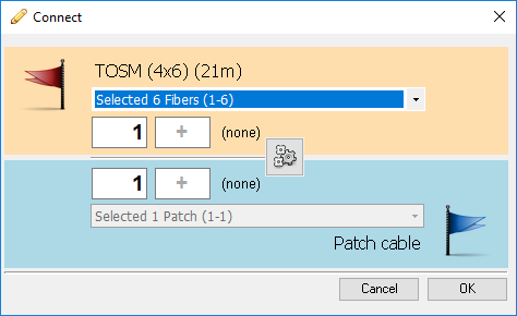
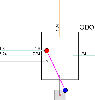
Patch cable to a patch panel or a splice-box
This example shows patch cable (black) that is already connected to a splitter and grey square that enables connecting to a FDB ports or its splice-box. Patch cable end is selected first (red circle) and grey square is selected second (blue circle). |
|
The program shall offer to connect patch cable to a module of our choice. Pay attention that the patch cable was already terminated in the splice-box. The program will disconnect it and than terminate it to a connector of our choice.
|
|
Next two cases shall have the same result. Whether we connect free fiber to a symbol of incoming splitter connector...
|
|
... or to other end of the patch cable already connected to the connector... we shall get the connection from fiber to that connector. Connection shall be achieved through the patch cable that is already connected to splitter connector.
|
|
In both cases the program shall offer to connect the fiber to an existing patch cable.
|
|
Cable to splitter connectors
Image on the right shows group
of fibers Fibers are selected first (red circle) and splitter connectors are selected second (blue circle). |
|
Connect window shall offer cable fibers (1-6) and splitter outgoing ports.
|
|
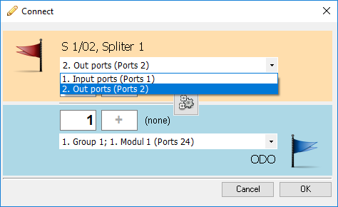
If needed outgoing ports can be replaced with incoming port(s). That is done by selecting "Input ports" item from the drop-down menu located on the blue flag area cause in this case it refers to splitter. |
|
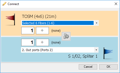
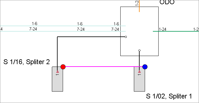
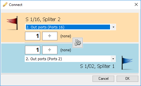
Splitter to splitter
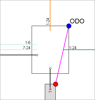
Image on the right shows connection in making between two different splitters.
|
|
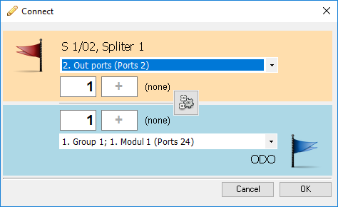
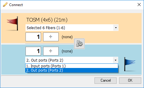
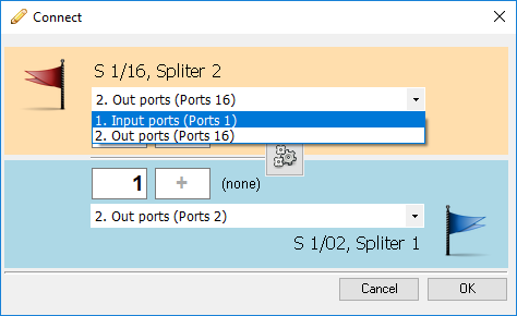
In both cases Connect window shall offer outgoing ports of both splitters.
|
|
On one of the splitters (second order splitter) we need to select "Input ports" from the drop down list. After that we insert numbers of ports that we want to connect. The connectors will be connected with patch cable within FDB.
|
|
Splitter connectors to a FDB patch pannel ports or to its splice-box
Image on the right displays connection in making between splitter connectors (grey square currently covered with red circle) and a FDB patch pannel connectors (grey square currently covered with blue circle).
|
|
Connect window shall offer outgoing ports of the splitter and connectors of the FDB's first module.
|
|
If there is a need outgoing ports can be replaced with incoming ones.
|
|
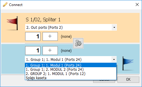
Also, we can replace a module or even choose the splice-box. After this we fill in input fields with numbers of ports that we want to connect. Connectors shall be connected with patch cables within FBB. Note: In this case it is not possible to use ports that have fibers already connected to them. Program will report an error if we try.
|
|