Symbol - NID (aerial line)
| Command: | 1 User
2 Users 3 Users 4 Users 5 Users 6 Users 10 Users |
| Menu path: | Users > Symbol - NID (aerial line) > (One of the above commands) |
| Icon: | 
 | |   |
|   | | 
 | |   |
|   | | 
 |
| Functional description: | Drawing the NID (Network Interface Device) at a desired location. |
Drawing the NID is a process in which we define the spatial position of
the NID symbol.
There are no prerequisites for drawing NID symbols.
In other words, the NID symbol can be drawn in a completely empty
drawing.
By running one of the commands (1 user,
2 users ... 10 users),
draw the NID with predefined capacity at a desired location. In addition
to capacity, the drawn NID will have defined:
- NID (aerial line) type (which corresponds to the capacity)
- purpose of the building (in which there is a NID)
- year of construction
Further data has to be entered through the Properties
window and / or through
UsersForm window opened by command Users
> Modify data in NID (aerial line).
You can modify the entered data at any time during the operation.
Procedure
In the example we’ve explained setting up the NID with capacity 1.
The setup process is the same for all the abovementioned commands (capacities).
From the main menu run Users >
Symbol - NID (aerial line) > 1 user
command. The command is now activated.
The cursor is displayed as „+” (plus) with the text
next to it asking you to indicate the desired location for drawing
the NID symbol (Figure 1).
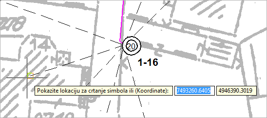
Figure 1
Left-click on the route point.
The NID symbol is being drawn (Figure 2).
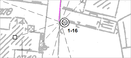
Figure 2
Properties
|
Figure 5 |
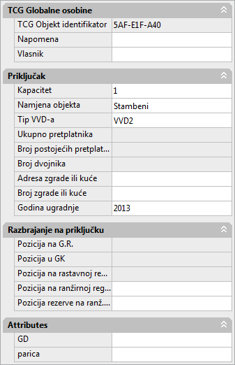
| Warning: |
Although the input field Attributes > Label is enabled,
entering new values won’t cause any real changes of attributes. |