Command: Fiber Info
| Command: | Fiber Info |
| Menu path: | TeleCAD-GIS main menu: Fiber Optics > Fiber
Info
TCG Map-Optics: right-click on the map element, then run the command Cable Fibers (for cable) or Node Fibers (for splice points and terminals) from the context menu. |
| Icon: | 
 |
| Functional description: | The command shows data associated with the fiber circuits. |
Fiber Info command opens (one of three possible)
window which show fiber circuit (logical fiber) data.
The window is used for overview only, whereas data entry and changes are made on Tab: Fiber details.
Command: Fiber Info
Fiber Info command can be run on:
- Site plan drawing (DWG drawing) - Fiber Optics > Fiber Info command.
- Map (TCG Map-Optics) - right-click on the cable or nodal element, then run the command (Cable Fibers or Nodal Element Fibers) from the context menu.
Depending on which network element is selected, the command opens one of the following windows:
|
Figure 1 |
|
Figure 2 |
|
Figure 3 |
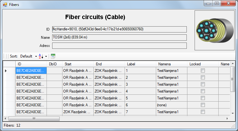
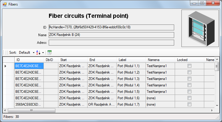
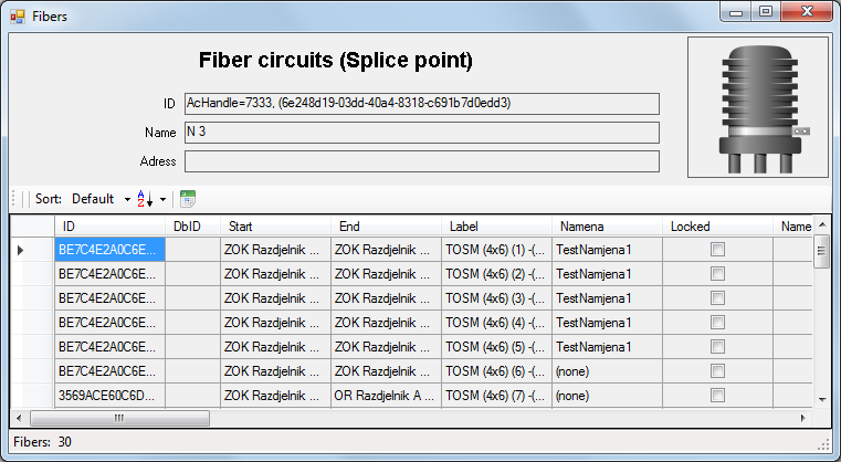
Windows: Fiber circuits (...)
All three aforementioned windows contain the same type of data, but
show only those fiber circuits passing through or terminated in the selected
element (cable, terminal or splice point).
In other words, if the cable is selected, only fiber circuits passing through
the cable will be shown, and if the splice point is selected, only fibers
spliced or terminated in the splice point will be shown, and finally,
if the terminal is selected, only fibers terminated on the terminal will
be shown, as well as those passing through it (e.g. fiber circuits connected
with patch cables).
At the top of the window the following data are displayed:
- ID (of the selected element) - various ID numbers (from the database, drawing...)
- Name (of the selected element)
- Address (of the selected element)
All the way to the right, at the top of the window, there is an image, the symbol of the selected element, so that the user would easily recognize if it is the cable, splice point or terminal.
Below the top of the window there is a table whose header has a toolbar (basic menu):
 -
Sort
-
Sort
Data sorting according to one of the following columns:- Default
- Fiber ID
- DbID
- FiberName
- LinkID
- Start
- End
 -
Sort order
-
Sort order
Determines the sorting direction:- Asc - Ascending
- Des - Descending
 -
Export to Excel
-
Export to Excel
Exports the table into the “xlsx” file
The table contains fiber circuit data.
Data on start and end fiber node as well as fiber circuit name are among
the most important data which are used to recognize which fiber is in
question.
The data which can be stored on the fiber circuit are given in the following chart:
| Attribute | Description |
| ID | Fiber circuit ID in TeleCAD-GIS. |
| DbID | Fiber circuit ID in GIS database of INOVA GIS Platform. |
| Start | Start nodal element of the fiber circuit. |
| End | End nodal element of the fiber circuit. |
| Label | Label (depends on the context in which the command has been used):
|
| Circuit name | Fiber circuit name |
| Locked | Indicator showing that the fiber is locked (when the fiber is locked no fiber changes are possible). |
| Name | Fiber name (arbitrary) |
| Info | Information on fiber circuit |
| Owner | Fiber owner |
| LinkID | Fiber circuit (link) ID which the observed fiber uses in the external system. It is used for matching with fiber circuit ID within INOVA GIS Platform with the purpose to integrate the two systems. |
| Lease UserID | ID of the user to whom the fiber has been leased. |
| Lease Start | Lease commencement date. |
| Lease End | Lease expiry date. |
| Lease Info | Information about fiber circuit lease. |
| Loss | Total attenuation along the fiber (entered manually). |
| Length | Optical fiber length (entered manually). |
| OTDR | Indicator showing that the fiber circuit has data on lengths
between the nodal elements of the fiber circuit obtained by measuring
in the field.
If there is an OTDR button, there are data as well. Clicking the button opens OTDR Trace tool so that the observed fiber circuit OTDR data can be edited. |