Working with errors
If there are errors in the network topology, we can detect them in two ways in the schematic diagram.
The first way
By running Check Errors
( )
command from the toolbar.
)
command from the toolbar.
After we click on the Check Errors icon (),
the schema displays only fibers with errors.
Other fibers will not be displayed. Nodal elements will remain visible
(Figure 1).
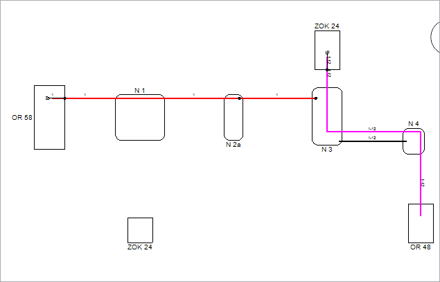
Figure 1
The second way
Select Errors
item in Analysis tab on the Docker.
By selecting Errors
item, the correct fibers will be displayed in light gray color.
Fibers with errors will be displayed in vivid colors (Figure 2).
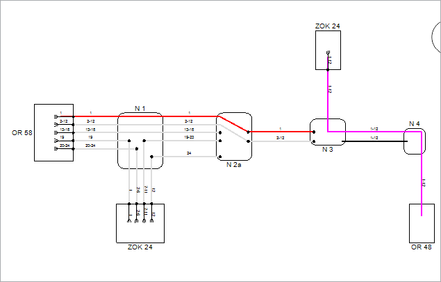
Figure 2
In whichever way we detected the errors, we further process them by
first checking the type(s) of errors.
We do this by opening General tab on Fiber Info window.
The window can be opened in two ways:
- By double-clicking on selected fiber (or group of fibers).
- by right-clicking on the fiber (or group of fibers) and running Fiber Info command from the context menu.
Window: Fiber Info
In the Fiber Info window, the General tab has two frames:
- Circuit Name and
- Warnings
Circuit name
If the circuit name along the fiber circuit is not consistent (elements
of one fiber circuit have different circuit names), there will be three
question marks (???) in the “Circuit Name" field.
At this point, the circuit name over the entire fiber circuit can be properly
defined in the way described on Fiber Circuit
Name page.
In addition, “Inconsistent circuit names” message will be displayed within
the “Warnings”, with a list of fiber circuit names detected along
the fiber circuit.
Warnings
If there are topological errors (including errors in the fiber circuit
name), they will be listed in the "Warnings".
In addition to errors of type: “Inconsistent circuit names", which
can be corrected on the spot, errors are corrected by returning to the
schematic diagram and taking necessary steps depending on the type of
the detected errors.
Errors can be the following:
Error |
Description |
Unallocated cable fibers |
If none of the cable fiber strands
are spliced in nodal elements at both ends of the cable, then
the program displays this warning. This is an allowed situation
and such cable will easily be sent to the GIS database. |
Unmatched circuit name |
Fiber circuit name is not consistent
along all fiber circuit elements, i.e. not all elements of the
fiber circuit have the same circuit name. |
Fiber is not properly terminated on the port/splice |
If the at least one cable fiber strand
is spliced at one end of the cable, then all other fiber strands
of that cable have to be spliced at both ends of the cable. You should bear in mind: if the user completes the splicing
of at least one cable fiber, the program will automatically splice
all other unallocated fibers in the splice point (splicing in
slice point) or splice box (splicing in the distribution frame)
at that end of the cable. The other end of the cable remains non-spliced. |
Partially displayed fiber in the scheme |
The scheme does not display all elements
of the fiber. This error applies only to the schematic display
directly “overviewing" the cables in the database. It does
not apply to the schematic display generated based on the site
plan infrastructure (DWG drawing). |