FDB Structure Organization
FDB Structure Organization
TeleCAD-GIS enables organization of FDB inner structure.
This means that it is possible to:
- Add or remove modules and groups (i.e. shelves, verticals) of a
patch panel
- Move occupied connectors together with its fibers from one module
to another
- Add and remove devices within FDB
- Make a copy of a device
- Move occupied connectors together with its fibers from one device
to another
*Direct change of module/device capacity is not possible but it is possible
to replace them with new ones of a different capacity and than to move
previously established connections from one to another.
| *Explanation: |
Direct change of module/device capacity is not possible
because TeleCAD-GIS depicts real world conditions where it is
not possible to change capacity of physical elements, however
they themselves can be replaced with new ones. |
| Warning: |
Check port ocupancy
Every time you make change to a FDB (or to similar objects)
structure, it is necessery to check port occupancy of the element
in a GIS database.
To do that use GIS database
> Refreshing port connectivity information command.
FYI, this command is active only for objects loaded from the GIS
database. It is disabled for newly added objects.
Ažuriranje oznaka
If the new capacity display of a FDB Site
plan label or a display on the Properties
window is not updated, call Tools
> Update labels command.
|
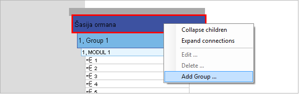
Add a group, shelve
or vertical |
Right-click on a cabinet chassis
or the grey bar above it to open context menu. Now call Add Group... command.
|
|
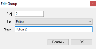
Edit group
window opens. On it, enter group's ordinal which will determine
position of a group.
From the drop-down menu select an item that determines whether
it is a group, shelve or a vertical.
In the end - name the element.
Group, shelve or a vertical is now created and we are expected
to add modules with connectors to it. |
|
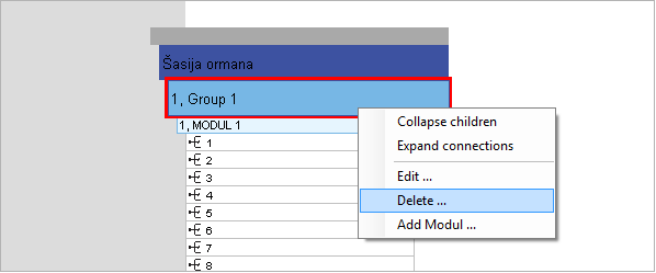
Delete a group,
shelve or vertical |
Precondition for deletion of
group, shelve or vertical is that none of the ports it contains
are occupied.
So, in order to delete this element we must first disconnect
all fibers and patch cables from connectors within the group or
we must move them to another element.
To delete a group - right click on a group, shelve or vertical
and open context menu. From it run the Delete...
command. |
|
|
|
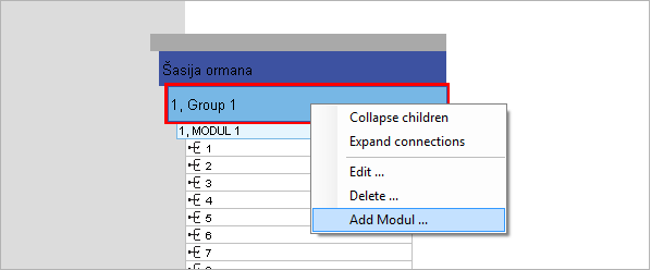
Add a module |
To add a module - right click
on a module's parent element (group, shelve or vertical) and open
context menu. From it run the Add Module...
command.
|
|
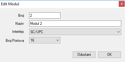
Edit Module
window opens. On it, enter module's ordinal which will determine
its position within the parent group (...shelve or vertical).
Next, name the element.
From the drop-down menu select an interface (connector type).
In the end, from the drop down menu select the number of ports
for the module. Click on the OK button
to finish. |
|
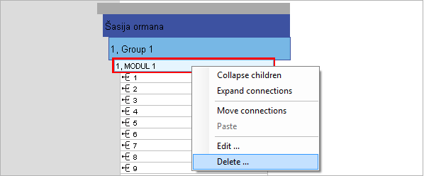
Delete a module |
Precondition for deletion of
module is that none of the ports it contains are occupied.
So, in order to delete this element we must first disconnect
all fibers and patch cables from connectors within the module
or we must move them to another element.
To delete a module - right click on a module and open context
menu. From it, run the Delete...
command.
|
|
Mapping of one
module's connectors to another |
Mapping of one
module's connectors to another module is mostly done when there
is a need to replace existing module with a new one of a different
capacity (be it bigger or smaller). Through mapping we actually
move connectors of one module to another without breaking connections
between connectors and cable fibers or patch cables. Once connectors
are moved we can delete the module of origin if we don't need
it anymore. Note that moving of connectors that are not occupied
is pointless because it is the fiber-connector
pair whose integrity we want to preserve when moving.
We always map (move) entire module. Target module must be of
the same or higher capacity than the capacity of module of origin.
In this case the transfer is guarantied.
Capacity of the target module can be smaller than the total capacity
of the module of origin but in this case the transfer shall occur
only if the number of the last occupied connector on the module
of origin is smaller or equal to the capacity of the target module.
Otherwise, the software shall report that it is unable to execute
the transfer (Massage: "Unable to relocate connections to
sync").
|
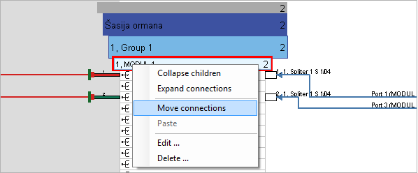
Mapping procedure:
Right-click on a module from which you want to move connectors
to open the context menu. From the context menu run Move
Connections command.
|
|
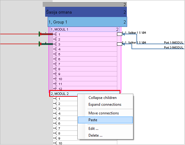
Once again, use the right-click,
but this time on the target (destination) module, to open the
context menu. From the context menu run Paste
command.
|
|
Program displays a warning
that connectors shall be moved and asks for confirmation.
Click on the Yes button to continue.
|

|
After this, connectors together
with their fibers and patch cables shall be relocated to selected
target (destination) module.
|
|
Given that the
direct change of existing module capacity is not possible, above
technique can be used to replace one module with another and thus
change the capacity of FDB:
- Create a new module with desired capacity and give it the
same name and interface as the one you are about to replace.
Use temporary ordinal (any that is not already used). Later
we shall change it to the ordinal of the module we delete.
- Move connections from existing module to the newly created
one.
- Delete the module of origin.
- Change the ordinal of the newly created module to the ordinal
that deleted module had.
|
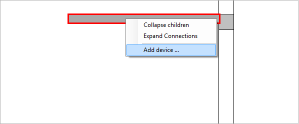
Add a device |
Right-click on a device type
bar or on the grey bar above it to open the context menu. From
the context menu run the Add Device...
command.
|
|
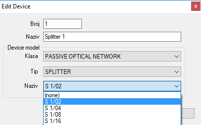
Edit Device
window opens where we define the device's position by entering
its ordinal in the number field.
Enter a name for the device and than from the drop down menus
select: class, type and name.
There are two classes:
- PASSIVE OPTICAL NETWORK
- ACTIVE OPTICAL NETWORK
If we select PASSIVE OPTICAL NETWORK item, in the next step
(Type) we shall be able to select "Splitter" and than
splitter capacity (Name).
|
|
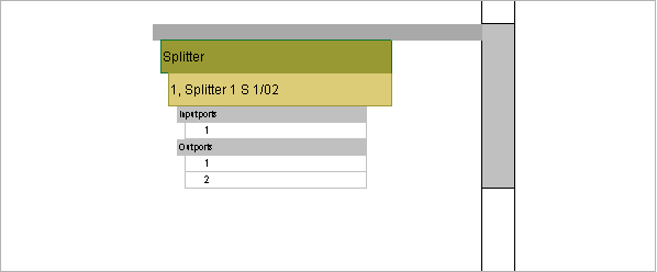
The device will be created
after we click on the OK button.
(Note: In a similar manner we can create passive and active
devices (OLT, ONT...))
|
|
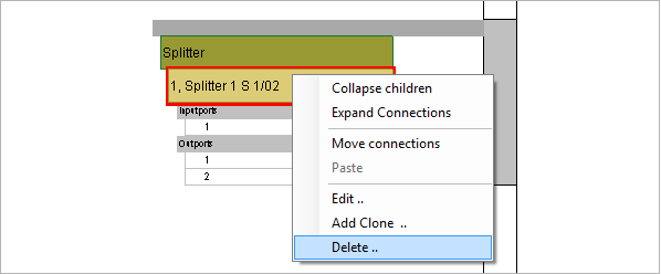
Delete a device |
Precondition for deletion of
a device is that none of the ports it contains are occupied.
So, in order to delete this element we must first disconnect
all fibers and patch cables from connectors within the device
or we must move them to another element.
To delete a device - right click on a device and open context
menu. From it, run the Delete...
command.
|
|
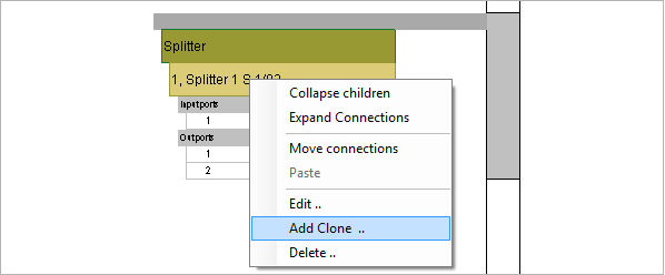
Clone a device |
Cloning is a process of creating
a new device with almost same properties as the device being cloned.
Exception is in the device's ordinal (which is logical since they
cannot be at the same place at once) and a devices name.
Cloning is, in fact, a fast way to create a new device.
To create a device's clone: right click on a device you wish to
clone and run Add Clone... command
from the context menu.
|
|
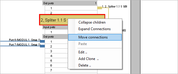
Mapping of one
module to another |
Mapping of devices
is similar to mapping of modules which is described in more details
so you should look into it too (see module
mapping).
|
Procedure:
Right-click on the device from which you want to move connectors.
Context menu shall open. From the context menu run the Move Connections command.
|
|
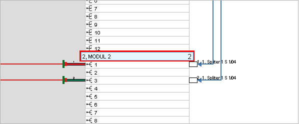
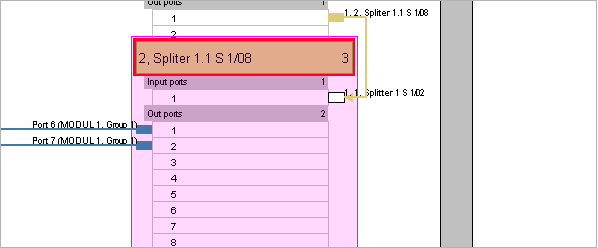
At that point, device is marked
red.
On the context menu, Move Connections
command is checked.
(Note: If you want to cancel the process simply uncheck Move Connections command.)
|
|
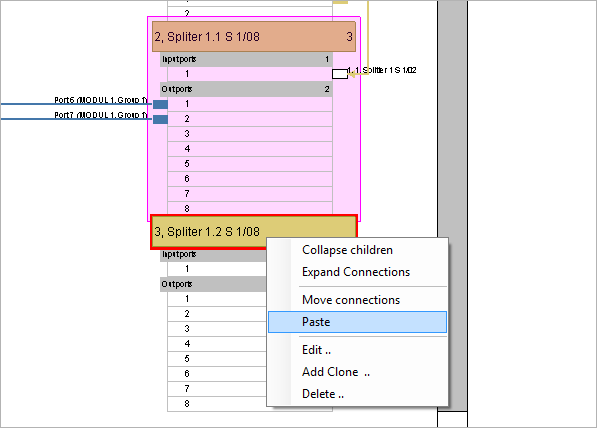
Now, oce again use the right-click,
only this time on a destination device, to open the context menu.
From the menu run the Paste command. |
|
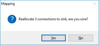
Program informs us that the
connections will be moved and asks for confirmation.
Click on the Yes button. |
|
After this, the connectors
together with cable fibers and patch cables connected to them
shall be moved to selected device.
Note: Mapping is possible only between devices of a same type
(e.g. from splitter to a splitter but not to a OLT).
|

|
|