Digitized Object
| Command: | Convert to TCG building |
| Menu path: | Buildings> Convert to TCG building |
| Icon: | 
 |
| Functional description: | This command converts vector polylines, created using one of CAD tools, into a GIS TeleCAD building structure. |
By using Buildings > Convert to TCG building command,
convert AutoCAD polyline into a TCG building structure.
When doing so, the polyline doesn’t have to be closed, and TeleCAD-GIS
will automatically:
- close the polyline
- add hatching and
- add box thet displays the house number
During the process, the user enters properties (e.g., address, number...) to the TCG building structure.
These data are one of the main reasons to convert the polyline into
a TCG building structure, as unlike polylines,
TCG buildings contain data not only related to the geometry.
In addition, when sending to GIS database, only TCG objects (not AutoCAD
objects) are being sent.
Generally, TeleCAD-GIS only works with TCG objects; everything else in the drawing is only of auxiliary character.
Procedure
Suppose that we have a rectangle (polyline) in the drawing representing
the building basis.
This rectangle is drawn manually by command Polyline
or perhaps even copied from another drawing (e.g. some vector city map).
Such a polyline (object type = AutoCAD object) has to be converted into
a building (object type = TCG object).
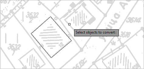
From the main menu run Buildings > Convert to TCG building command. The command is now active.
The cursor is displayed in
aform of a small rectangle (You can select multiple polylines at once and all the new buildings will, through the window Construction of Building (Figure 4), be assigned with the same properties.) |
Figure 1 |
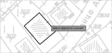
Select the polyline by left-clicking the mouse (Figure 2). |
Figure 2 |
When the first polyline is
selected, proceed with selecting the other ones (if any). (In the example we’ve selected only one polyline (Fig. 3)). |
Figure 3 |
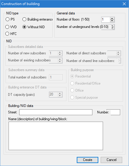
After right-clicking the Construction of Building window opens (Figure
4). The window is used to enter |
Figure 4 |
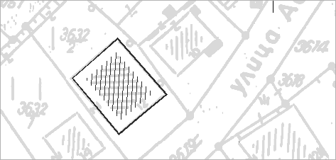
After filling in the data in
the Construction of Building window,
by clicking on Create button, generate
the |
Figure 5 |