Understanding forms
In order to make changes, the user has to understand the nature of AutoCAD
objects constituting the header and the data table.
They are the following objects:
- Lines and polylines - (forming the header or table)
- Text - (plain text)
- Attributes - (text fields that are dynamically filled)
- Wipeout object - (special type of raster image that inherits the workspace background color)
- Logo
The logo can be constituted of several different types of AutoCAD objects.
(INOVA’s logo contains lines, polylines and hatches, but other objects can be used too.)
Apart from that, it is necessary to define the insertion point of the form.
Lines and polylines
Lines and polylines are used for drawing
the table or header.
If a change is required, do it in the standard AutoCAD manner.
Text
Plain text. In the layouts it is shown as it is.
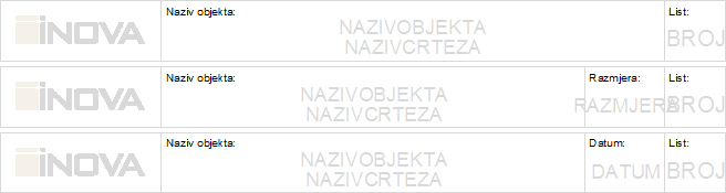
Figure 1
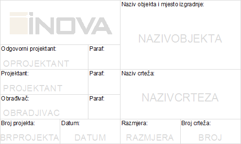
Figure 2
Attributes
Attributes are textual fields which are filled dynamically.
E.g. where it says “DRAWINGNAME", it should be the actual name (e.g.
“Distribution Terminal Site Plan 1-4”).
You mustn’t change the names of the attributes. You can change their size
and location.
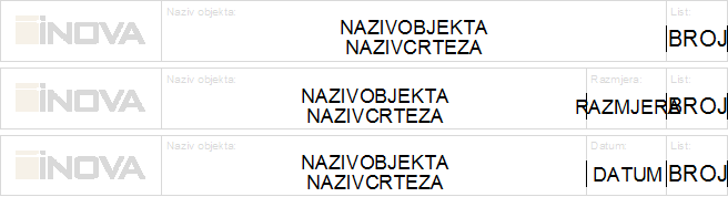
Figure 3
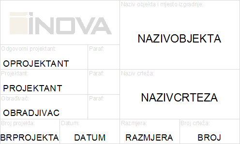
Figure 4
Wipeout object
Wipeout object is used as the background of the table in which the data
are displayed.
Wipeout is always in the same color as the background of the drawing workspace.
Appearance of the header with wipeout object (Figure 5).
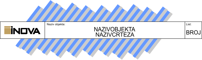
Figure 5
Appearance of the header without wipeout object (Figure 6).
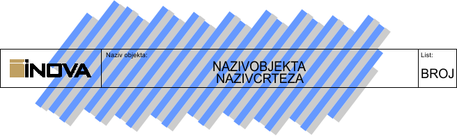
Figure 6
If the user resizes or moves the table, the same has to be done with
the wipeout object.
(Wipeout object can easily be overlooked as it is in the color of the background,
and if it’s frame is turned off then it can’t even be selected.)
To manipulate the wipeout, you need to turn its frame on (similar as
with the raster).
Since 2012 version of TeleCAD-GIS, this frame is automatically turned on
when running one of the commands from the submenu Layouts
> Set Form.
If you work with another TeleCAD-GIS version or the frames are turned off
for any reason,
you can turn them on from the command line in the following way:
- Enter wipeout in the command line and press ENTER key.
- Specify first point or [Frames/Polyline] <Polyline>: f , and then ENTER.
- Enter mode [ON/OFF] <OFF>: on , and then ENTER.
After this, the wipeout object will be visible and you’ll be able to manipulate this object.
Logo
Logo can be made of various AutoCAD objects (lines, polylines hatches,
texts, etc.)
It is important to note that the logo must be made of vector objects.
Never insert raster images.
When you insert a raster image in the DWG drawing, it does not become
an integral part of the DWG file.
Inside the DWG file, there’s only a reference indicating the disk location
where AutoCAD will search for that raster image.
If such a DWG file is sent to another computer, raster images will not
be visible (and therefore the logo will be incomplete or not visible at
all).
(Find out more about raster images on Classic
Management page.)

Figure 7
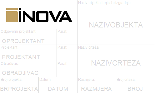
Figure 8
Insertion point
After you made changes to the form (table
or header), you need to define the insertion point of the form.
Insertion point of the header must
be in the top right corner of
the header.
Insertion point of the data table
must be in the bottom right corner
of the table.
If you save changes using Set Form > Save form changes command, the program will automatically detect and specify the insertion point of the form at the previously described places based on the form type.