Loading optics from GIS Database
This page describes the procedure of loading FO network elements into the schematic display, and then into the site plan (DWG drawing).
It is desirable that you previously study Window: DB Optic View.
Procedure
From the main menu run TCG Map - Optics command.
DB Optic View window opens (Figure 1).
When first opening the window, only the map is displayed (later we will open the schematic display too).
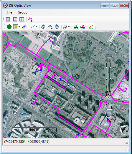
Figure 1
Set your position on the map where FO network infrastructure is located (the one that interests you).
Left-click to select the cable and/or the nodal element. Cable and/or nodal element turns red (Figure 2).
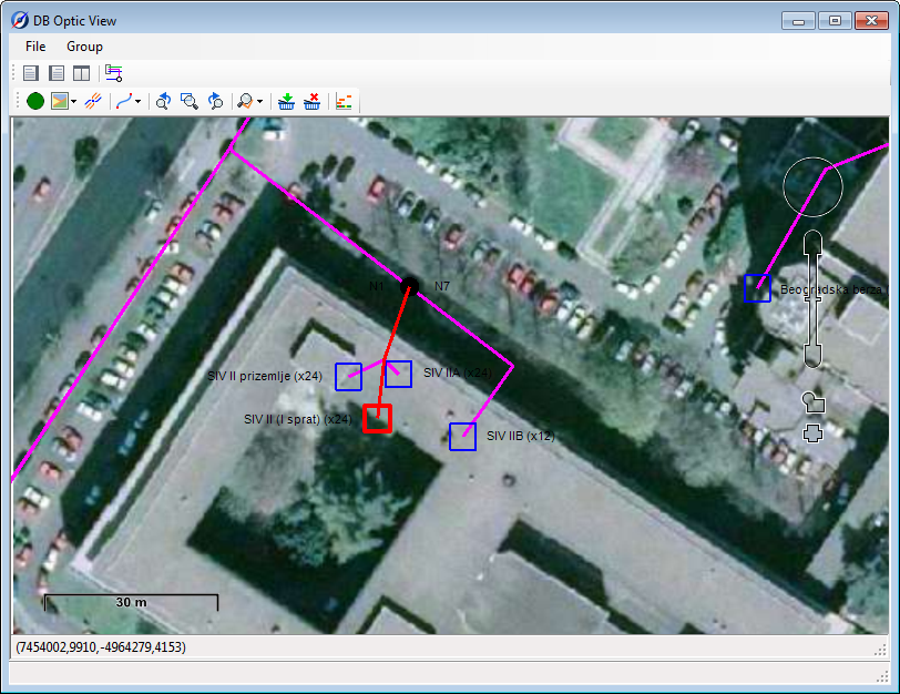
Figure 2
When the cable and/or nodal element is selected click on Add to Basket ( ) to add them to the “basket”.
On the map, FO cables added to the “basket” are displayed in bold blue line, and
nodal elements (splice point, ODF, etc.) added to the “basket” are framed with a blue semi-transparent square (Figure 3).
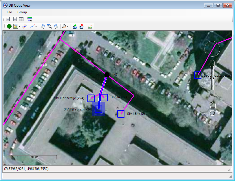
Figure 3
When you’ve added the elements to the “basket”, click on Create Scheme from Selected Objects ( ) to generate the schematic display. At that point, schematic display window opens, now set parallel to the map (on the right). Elements from the “basket”, previously filled with FO network elements, are being loaded into it (Figure 4).
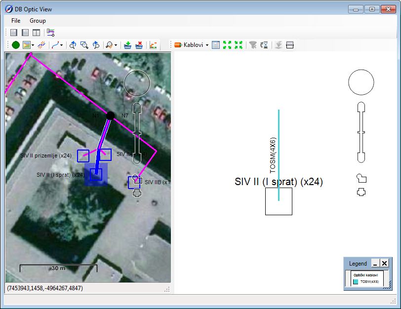
Figure 4
In this way, it often happens that not all network elements necessary for further work are loaded.
To complete your scheme, you need to load additional network elements.
That can be done by repeating the above described procedure with new elements or in one of the following ways:
- Right-click on the cable (while in Cables mode) and run Load all nodal elements of the cable.
The command loads nodal elements that are at the cable’s ends.
(When sending to GIS database, each cable has to have the nodal elements loaded, otherwise the program reports an error)
- Right-click on the cable (while in Cables mode) and run Load all fibers of the cable.
This command loads all the fibers passing through the cable. All elements through which the fibers pass are loaded along with the fibers.
- Right-click on the fiber (while in Fibers mode) and run Load all affiliated elements of the selected fiber.
This command loads the selected fiber (or group of fibers). All elements through which the fibers pass are loaded along with the fibers.
Fibers that are completely loaded in the scheme are displayed in a full line, and fibers which are incomplete (some fiber elements are in the GIS database but not in the scheme) are displayed in a dotted line.
When you fully create the scheme, i.e. when the scheme contains all the necessary elements, you can move on to loading infrastructure in the drawing (site plan).
There are two options:
- You can load into the drawing all the elements previously loaded in the schematic display (i.e. displayed in the scheme) (File > Export to Drawing).
- You can load into the drawing all the elements selected in the schematic display (i.e. displayed in the scheme) (File > Export Selected to Drawing).
Loading into the drawing is started by running File > Export to Drawing or File > Export Selected to Drawing command (they’re both located on the main menu of DB Optic View window). After the loading process, network elements are displayed in the site plan (DWG drawing).