Innerducts
| Command: | Innerducts |
| Menu path: | Conduit > Innerducts |
| Icons: | 
 |
| Functional description: | The command lays down an innerduct with the property "designed", along user defined path. |
Innerducts laying is a procedure whereby innerduct path is defined by selecting
route-points,
and the program generates the innerducts by accepting the defined path.
The path is defined by the selected points connected along the shortest
possible path.
A precondition for innerducts laying is to have trench routes in the
site plan (other TeleCAD-GIS objects are not required).
Innerducts are drawn along the routes in the site plan drawing.
Innerduct drawn in this manner has the following properties:
- Duct type: Innerducts
- Duct Bank Status: Designed
- Number of rows and columns of innerduct: 0 (user is expected to enter the value for these attributes)
Other features either need to be entered subsequently or defined through
the system settings.
All the attributes can be changed later through the Properties
window.
Laying procedure
From the main menu run Conduit > Innerducts
command.
The command is now active. The cursor is displayed in a form of plus sign
(“+”) with a message
next to it instructing you to Select route-point
(Figure 1).
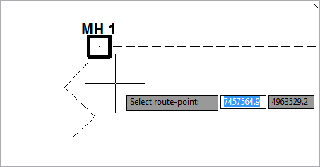
Figure 1
By left-clicking on the route-point or on the manhole symbol outline,
select the point (Figure 2).
By left-clicking select the center of the manhole (this is the insertion
point of the manhole symbol and it is supposed to be located on a route-point).
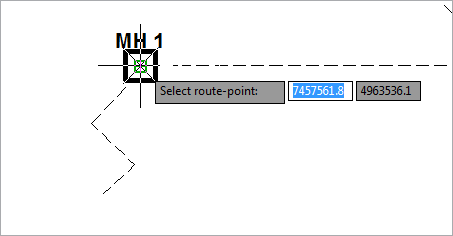
Figure 2
After clicking, the first selected point is marked with the "X"
sign,
and the program instructs you to indicate the next point.
By clicking on the next point, a new "X" sign appears (Figure
3).
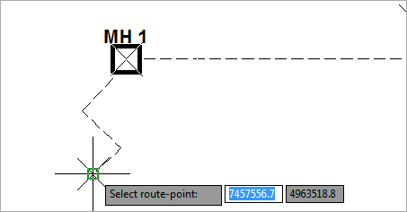
Figure 3
The path joining the selected points (marked with “X”) is the path along
which the innerducts will be generated.
Number of points for defining the path is not limited.
End the command by right-clicking or pressing the ENTER key.
Innerducts are generated with an corresponding label (Figure 4).
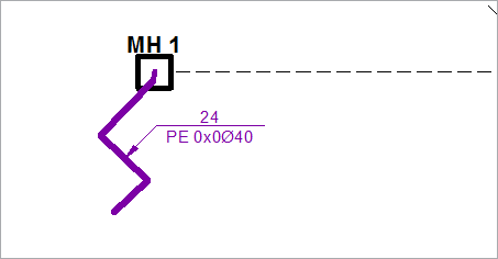
Figure 4
Properties
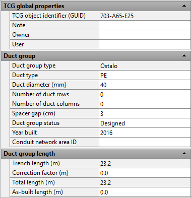
The properties of the newly created innerducts can be changed through the Properties window (Figure 5).
Entering and changing properties through the Properties
window is the same for all types of duct bank including innerducts,
and they are explained on Duct Bank
Properties page.
Additional information on the principles of linear infrastructure laying
in TeleCAD-GIS
are on Laying Linear
Infrastructure page.