Laying IFC Cable
IFC cable can connect two peces of equipement (e.g. ODFs) within a building.
The connection is made while in Edit
ISP window.
Procedure
First run Edit ISP
command.
The program expects us to select a building (Figure 1).
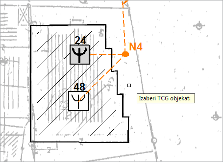
Figure 1
Inside plant view is opened by clicking on the building outline (Figure 2).
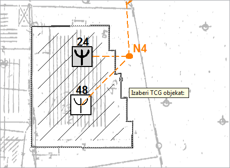
Figure 2
After clicking it, Edit ISP window opens (Figure 3).
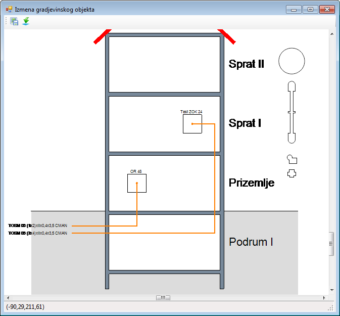
Figure 3
The window shows the same two ODFs which are within the building symbol
on the site plan.
Cables (from the site plan) are shown next to them.
| Note: |
ODFs are initially arranged in the ground floor. In the example, one ODF was relocated to the 1st floor. Besides that, cables are automatically connected to proper ODFs. The program does that only if it knows for sure how to arrange the cables, otherwise they remain non-arranged (see Window: Edit ISP page). |
IFC cable
Right-clicking on one of the ODFs we would like to connect opens the context menu from where we run Add IFC Cable command (Figure 4).
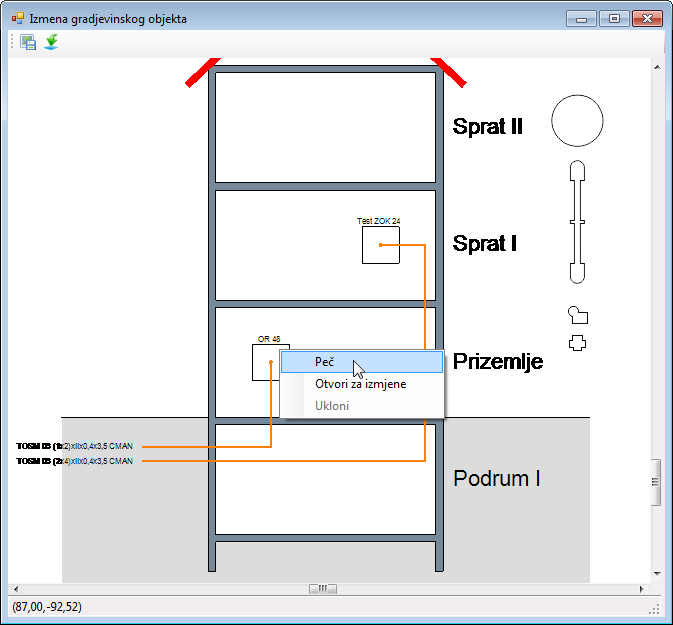
Figure 4
IFC cable (represented with orthogonal polyline) is generated (Figure
5).
The cable end is located on the ODF from where the command has been activated,
but is not arranged on the port within that ODF.
In order to connect it to the port (connector), Open
to Edit command should be run (later on).
The other cable end should be laid on the ODF with which we wish to
connect the previous ODF.
Take cable end (green point) and carry it towards the ODF (“Test OTB 24”
in the example).
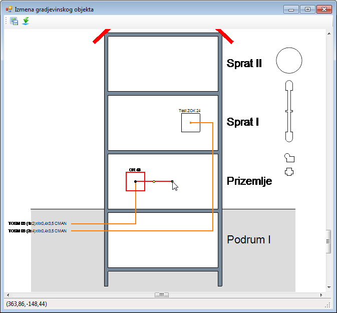
Figure 5
While carrying the cable end, the cursor changes its shape (Figure
6), letting us know that we are in the area where we cannot drop the cable
end.
The cursor remains such until the mouse is on the ODF.
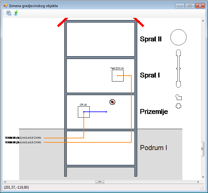
Figure 6
When on the ODF, the cursor lets us know that the cable end can be dropped now (Figure 7).
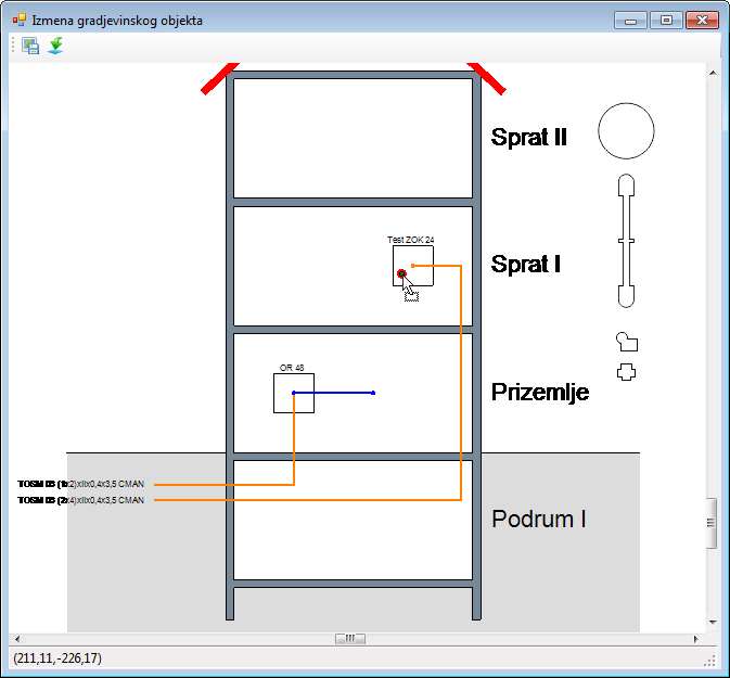
Figure 7
After the mouse is released, the IFC cable is drawn between two ODFs (Figure 8).
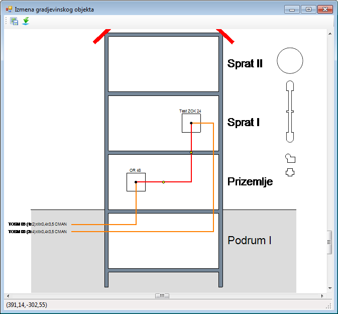
Figure 8
Drawn orthogonal polyline at this point represents only one IFC cable,
but it can represent multiple patch cables as well.
If we wish to increase the number of patch cables represented by the polyline,
it is done in Intra-facility Cables window.
It is opened by double-clicking on the polyline that represents patch
cable (as described in detail on Intra-facility
Cables page.)