Window: Edit ISP
In Edit ISP window arrange and connect
TC infrastructure elements within the inside plant. Cables can be connected
to ODFs in the same manner as it is done outside the building when “Fiber
Splicing” command is used. Besides that, two ODFs can be connected with
patch cables (this is done only within the inside plant). Elements can
be arranged along the floors and within the same floor.
Edit ISP window opens by running Edit ISP command.
Window: Edit ISP
After running Edit ISP command, Edit ISP window opens (Figure 1).
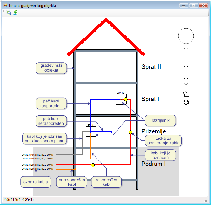
Figure 1
The window includes toolbar:
 Save Changes - saves
changes made in the window.
Save Changes - saves
changes made in the window.
If the changes are not saved, the program will ask us to do that if we wish while closing the window. -
Export to Block -
-
Export to Block -
The command is described in detail on Command: Export to block page
The elements of the window we work with are:
- Building levels
- Equipement (ODF, OTB...)
- Cables
- IFC Cables
Building levels
Floors and ground floor are levels above ground, whereas basements are
underground levels.
Equipment, cables and IFC cables are arranged along the levels.
If there is a need to redefine the number of building levels,
it is done as described on Building
page.
Equipment
Equipment (ODF, OTB...) are arranged along the levels or within the
same level by drag and drop technique.
Right-clicking on a equipement symbol opens the context menu (Figure 2)
from where we can run the following commands:
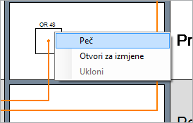
Figure 2
- Add IFC cable
Creates a new IFC cable within the building (see Add IFC Cable). - Open to Edit
Opens Fiber Splicing [distribution frame] window where the fibers and patch cables are arranged on the ports (connectors). - Remove
Removes equipement.
The command is active only if the equipement element is previously deleted from the site plan.
The equipement deleted from the site plan drawing is crossed with red X within the inside plant view.
Before deleting equipement from the site plan drawing, disconnect all the fibers connected to it.
Cables
Cables are shown by as orange orthogonal polylines.
These polylines can be manualy rearranged.
These are OSP cables whose one end is connected to the distribution
frame within the inside plant, and the other to the rest of the network
outside the building i.e. OSP.
This other end also has cable label (the same as the one on the site plan).
Right-clicking on a cable opens the context menu (Figure 3) from where
we can run the following command:
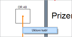
- Remove Cable
Removes cable from the inside plant view.
You should bear in mind that the cable will not be actually removed, because it is still present on the site plan drawing, and will be shown again when we open the inside plant view. The deletion makes sense only if the cable has been previously removed (deleted) from the site plan as well. In this case, it will be shown as gray polyline within the inside plant view because the inside plant itself has the record on its existence.
When working with the database, make sure that you have previously discinnected the cable from all distribution frame ports or feom the splice box. This needs to be done in all distribution frames and splice points where the cable was spliced/connected. Update the database with this new state. Load new state feom the database and only than delete the cable from the database.
Patch cables
IFC cables are shown usibng blue orthogonal polylines.
These polylines can be rearranged.
IFC cables connect two different peaces of equipement, both within the same building.
- Double-clicking
the IFC cable opens Intra-facility Cables
window.
It contains information obout the IFC cable (or cables), as well as tools for adding or deleting IFC cables.
Editing cable geometry (Polyline)
(general principles)
Regardless of which cables it is about, they are represented with orthogonal
polylines.
These polylines can be edited in following manner:
Select the cable by left-clicking on polyline representing it.
It becomes red, and there are also yellow dots in the middle of every cable
segment.
These dots represent grips, i.e. places on the cable which can be grabbed
using mouse and then cable segment can be moved.
In this way cable geometry can be arranged as required (the cable will
always take a turn under the right angle).
Cable ends can also be moved. Cable ends are represented with black
or green dot.
If the dot is green, the cable end can be moved, and if it is black, the
cable end cannot be moved.
Cables
The initial cable end (towards the OSP network) is on the left wall of the building, which is also a location of cable labels.
The other cable end (within the building) can be automatically positioned
on a distribution frame or non-arranged.
Cable end is positioned on the distribution frame automatically only if
the program knows for sure that the cable in on that very distribution
frame.
The program knows this if there is only one distribution frame on the route-point
(site plan) where the cable ends.
There can be multiple distribution frames within the building symbol,
on the route point where the cable (or cables) end.
In this case, the program cannot know which cable belongs to which distribution
frame. These cables are initially shown as non-arranged cables. The user
should then manually position the cables on the distribution frames.
IFC cables
Initially, one end of IFC cable is on the distribution frame from which
the command to create IFC cable has been run (right-clicking on distribution
frame > context menu > Add IFC Cable).
The other cable end is free and shown as a green dot.
This dot can be moved to any other distribution frame within the building.
Distribution frames are thus connected by IFC cable (read
more).
Drawn orthogonal polyline represents only one IFC cable, but it
can represent multiple IFC cables as well.
If we wish to increase the number of IFC cables represented by the polyline,
it is done in Intra-facility Cables window.
It is opened by double-clicking on the IFC cable polyline (as described
in detail on Intra-facility Cables
page.)