Window: Device Box [FDB]
Device Box window (fig 1) displays detailed
schematic diagram of FDB (Fiber Distribution Box) and allows us to connect
cable fibers to connectors within FDB as well as making further connections,
using patch cables, with various devices which can also be located in
FDB.
When it comes to fiber-optics access networks (GPON), FDB is used to accept
incoming fiber (coming from the CO) split it, using one or more cascading
splitters, and than forward it to cables connecting end users (drop).
Besides that, we can use this window to organize or reorganize the structure
of FDB itself. This includes adding new and/or deleting existing elements
within FDB (modules, splitters, devices...).
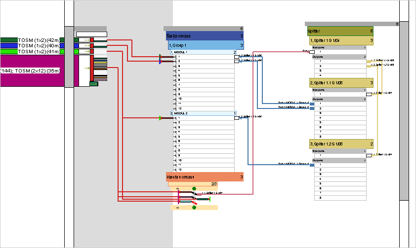
Figure 1
Window can be opened in following manner:
- by calling Splicing command
and than clicking on a FDB symbol on a site plan drawing or
- by double-clicking on a FDB symbol while we are on the schematic
diagram (i.e. TCG
Optic View)
| Tip: |
You can navigate through Device Box
window by using mouse wheel - roll to zoom (+/-) and press to
move working area (pan).
Double click on a wheel to zoom extent.
Level of details displayed depends on a zoom level - closer we
are - display is more detailed.
|
Window elements
Device Box window is divided into three
units:
- Cables:
On the left side there is a slide bar with a slider that contains all
available cables.
This means - all cables terminated at FDB be it incoming or outgoing
- Connectors and
splice box
Central part is reserved for connectors that accept OSP cable fibers
(on the left) as well as patch cables (on the right).
On the bottom we shall find splice box which is used to directly splice
fibers or to terminate unconnected fibers.
- Devices
On the right side there is a unit with devices (splitter, OLT, ONT...).
Patch cables that connect devices with patch panel or splice box (central
part) are located left from the devices.
Patch cables that connect devices to each other are located right from
the devices (i.e. cascading splitters).
All these units are displayed in a form of hierarchically organized
elements.
Note: Elements marked with (*) do not have corresponding equivalent in
the real world be it physical or logical.
These are merely TeleCAD-GIS auxiliary elements meant to facilitate ease
of use.
Cables:
|
Cables are shown in a form
of hierarchically organized elements:
- Slide bar*
- Slider*
- Group of all cables*
- Cable (individual)
- Buffer tube
- Fiber
Slider, which can be moved along the vertical axe, carries cables
with their sub-elements.
The purpose of the slider is to enable moving cables closer to
a location where the splicing is performed. Slider can be moved
by double clicking on a slide bar or by dragging the slider.
Cables, buffer tubes and fibers can be moved (drag and drop).
By moving elements that contain sub-elements, sub-elements are
moved too (i.e. by moving a cable, buffer tubes and fibers are
moved too.)
The splicing is performed by dragging a fiber(s) to a connector(s)
or to a splice points of a splice box.
|
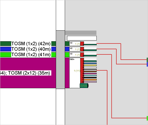
Figure 2 |
Connector panels: |
Connector panels are shown
in a form of hierarchically organized elements:
- Top bar*
- Chassis
- Shelve / Vertical / Group
- Module
- Connectors
Al elements except a connector can be expanded or collapsed
by a double click. This way we can adjust the display of elements
to the needs of current activity.
Context menu can be opened by right clicking on an element.
It contains commands that are described further down the text.
|
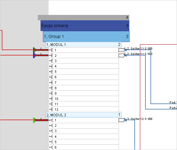
Figure 2 |
Splice box: |
Splice box is shown in a form
of hierarchically organized elements:
- Top bar*
- Splice box
- Splice box display bar
- "Green dot" - adds fiber splice point
- Splices
Al elements except a splices can be expanded or collapsed by
a double click. This way we can adjust the display of elements
to the needs of current activity.
Context menu can be opened by right clicking on an element.
It contains commands that are described further down the text.
|
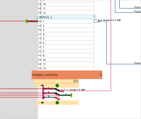
Figure 3 |
Devices: |
- Slide bar*
- Slider*
- Top bar*
- Device type
- Device: Splitter, ONT, OLT
- Grouping of type: In/Out
- Connectors
Slider, which can be moved along the vertical axe, carries devices
with their sub-elements.
The purpose of the slider is to enable moving devices closer to
a location where the splicing is performed. Slider can be moved
by double clicking on a slide bar or by dragging the slider.
Al elements except a connectors can be expanded or collapsed
by a double click. This way we can adjust the display of elements
to the needs of current activity.
Context menu can be opened by right clicking on an element.
It contains commands that are described further down the text.
|
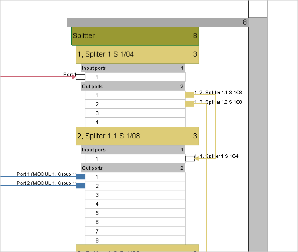
Figure 3 |
Usage
There are number of activities that can be performed while on the Device Box window.
Basic activities are:
(Instructions are on separate pages. Use offered links to access them.)
Commands
On the FO splicing schematic window
we can use number of commands.
They can be found at:
- Main menu
- Context menus (opened by
a right click on various elements)
- some commands are executed on a mouse
double-click.
Main meny:
File > Save
Saves the changes made on the Device Box
window.
File > Exit
Closes the Device Box window prompting us
to save the changes.
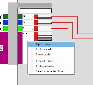
Context menus - right click on a...
...right
click on a Cable:
- Exclusive edit
Expands all elements of selected cable (i.e. buffer tubes and
fibers) so that they and their connections become visible
while collapsing all other cables. This way we can more easily
focus on the fibers we are working with.
At that moment, top bar displays Exclusive
mode off command that turns off this mode.
- Show cable
Locates and displays on a site plan selected cable. Cable on
the site plan shall also be selected at that point.
- Expand tubes
Expands all buffer tubes of the cable so that all its fibers
become visible.
- Collapse tubes
Collapses all buffer tubes and thus hides the fibers of the
cable.
Buffer tubes are still visible.
- Select connected fibers
Selects cable fibers that are terminated on FDB ports or in
its splice box.
Tip: by selecting in this way and than by dragging the fibers
back to cable (cable's white field) we can disconnect all
cable's fibers in one move.
While doing so, take great care not to unintentionally
disconnect fibers you did not mean to disconnect!
|
|
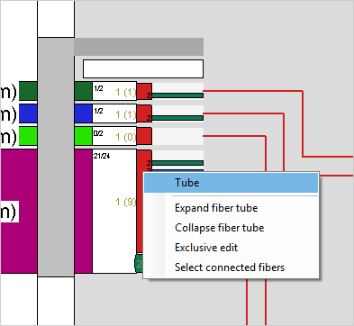
...right
click on a Buffer Tube:
- Expand fiber tube
Expands buffer tube so that all its fibers become visible.
- Collapse fiber tube
Collapses buffer tube and thus hides the fibers.
Buffer tube is still visible.
- Exclusive edit
Expands all elements of selected Buffer Tube (i.e. fibers)
so that they and their connections become visible while collapsing
all other cables and buffer tubes. This way we can more easily
focus on the fibers we are working with.
At that moment, top bar displays Exclusive
mode off command that turns off this mode.
- Select connected fibers
Selects buffer tube fibers that are terminated on FDB ports
or in its splice box.
Tip: by selecting in this way and than by dragging the fibers
back to cable (cable's white field) we can disconnect all
buffer tube fibers in one move.
While doing so, take great care not to unintentionally
disconnect fibers you did not mean to disconnect!
|
|
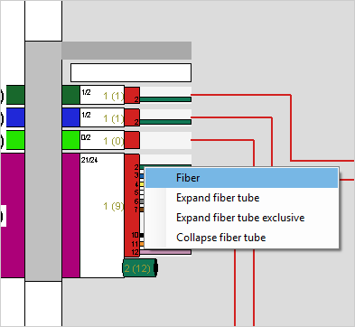
...right
click on a Fiber:
- Expand fiber tube
Expands fiber's buffer tube so that all its fibers and connection
paths become visible.
- Collapse fiber tube
Collapses fiber's buffer tube and thus hides the buffer tube
fibers.
Buffer tube is still visible.
- Expand fiber tube exclusive
Expands all elements of fiber's Buffer Tube (i.e. fibers) so
that they and their connections become visible while collapsing
all other cables and buffer tubes. This way we can more easily
focus on the fibers we are working with.
At that moment, top bar displays Exclusive
mode off command that turns off this mode.
- Collapse fiber tube
Collapses fiber's buffer tube and thus hides the fibers of
that tube.
Buffer tube is still visible.
|
|
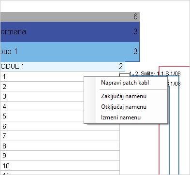
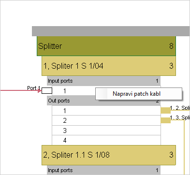
...right
click on a Connector:
- Create Patch (Napravi peč kabl)
Adds a patch cable (see more at: Adding
a patch cable)
- Zaključaj namjenu
(outdated, now performed automatically when adding fiber circuit
name)
- Odključaj namjenu
(removes newly added fiber circuit name or aborts changing
the existing one)
- Izmjeni namjenu
(see more at: Add
fiber circuit name)
- Učitaj vlakno (this command
is yet to be added!)
Loads fiber circuit connected to a connector in question (including
all elements along the fiber circuit (cables, terminals, splices...)).
All elements, as far as uninterrupted fiber circuit goes including
connections with patch cables are loaded into site plan drawing.
|
|
The following set of commands, that can be invoked from the context
menu, relates to several different hierarchically organized elements that
make FDB inner structure.
The role of these elements is to accept fibers of OSP cables and inner
patch cords. These are: patch panels, splitters, various other devices
etc.
The last element in this hierarchy is a connector (i.e. port) whose context
menu differs from these and is described earlier in the text (first passage
above).
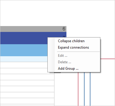
...right
click on a Top bar, chassis or Group (Shelf, Vertical)
- Collapse children
Collapses selected element so that all of his sub-elements
are no longer visible.
- Expand connections
Expands selected element so that his sub-elements become visible.
Expansion reaches last element in the hierarchy (i.e. connector)
but only for the elements with occupied connectors. If none
of the element's connectors are occupied the element won't
be expanded.
- Edit
Opens a new window where we can edit selected element's structure
and its basic data (e.g. name). More details can be found
at Organize FDB structure
page.
- Delete
Deletes selected element together with all its sub-elements.
Program won't allow deletion if just one element's connector
is occupied (all must be free).
- Add group
Adds new Shelve/Group/Vertical
- Add module
Adds new module.
Note:
Commends Edit i Delete
are only active for Shelve/Group/Vertical.
|
|
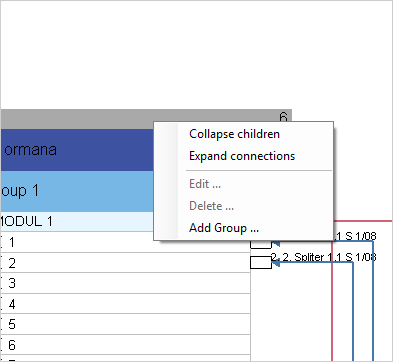
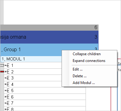
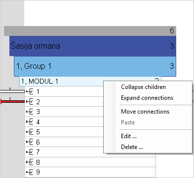
...right
click on a Module:
- Collapse children
Collapses selected element so that all of his sub-elements
are no longer visible.
- Expand connections
Expands selected element so that his sub-elements become visible.
Expansion reaches last element in the hierarchy (i.e. connector)
but only for the elements with occupied connectors. If none
of the element's connectors are occupied the element won't
be expanded.
- Move connections
Enables module reorganization. Reorganization is performed
by transferring the fiber-connector pair from one module to
another (see
more).
- Paste
Works in conjunction with Move connections
command (see
more).
- Edit
Opens a new window where we can edit selected element's structure
and its basic data (e.g. name). More
details here.
- Delete
Deletes selected element together with all its sub-elements.
Program won't allow deletion if just one element's connector
is occupied (all must be free).
|
|
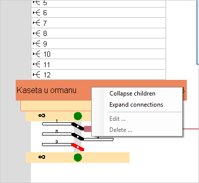
...right
click on a Splice Box:
- Collapse children
Collapses selected element so that all of his sub-elements
are no longer visible.
- Expand connections
Expands selected element so that his sub-elements become visible.
Expansion reaches last element in the hierarchy (i.e. splice).
- Edit
Command is disabled in this case.
- Delete
Command is disabled in this case.
|
|
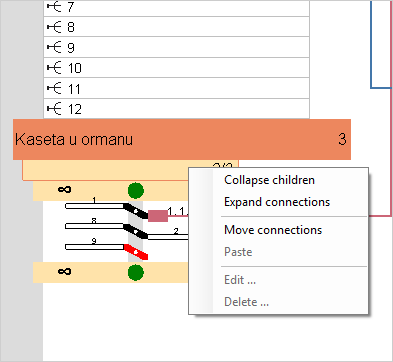
...right
click on a Splice box display bar:
- Collapse children
Collapses selected element so that all of his sub-elements
are no longer visible.
- Expand connections
Expands selected element so that his sub-elements become visible.
Expansion reaches last element in the hierarchy (i.e. connector)
but only for the elements with occupied connectors. If none
of the element's connectors are occupied the element won't
be expanded.
- Move connections
Enables transfer of connections from splice box to modules.
Reorganization is made by moving fiber-connector pair (see more)
- Paste
Works in conjunction with Move connections
command (see
more).
- Edit
Command is disabled in this case.
- Delete
Command is disabled in this case.
|
|
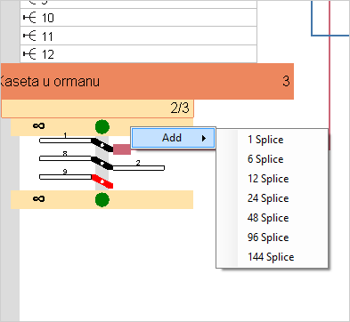
...right
click on a "Green dot" bar:
- Add > ...
Adds selected number (1, 6, 12...) of splices i.e. points where
splicing can be performed.
Note: By dragging a number of cable fibers or patch cables
to the left or right side of the green dot program automatically
generates required number of splices.
|
|
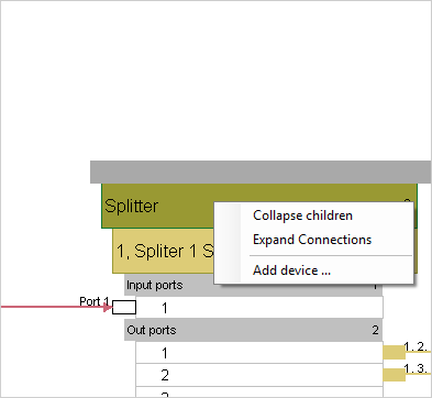
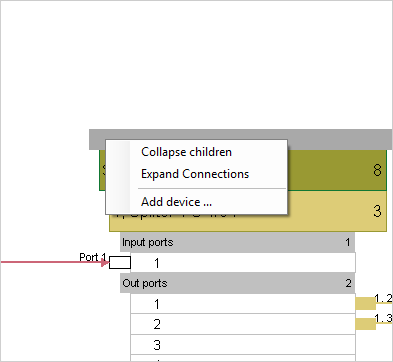
...right
click on a Device type or Top bar:
- Collapse children
Collapses selected element so that all of his sub-elements
are no longer visible.
- Expand connections
Expands selected element so that his sub-elements become visible.
Expansion reaches last element in the hierarchy (i.e. connector)
but only for the elements with occupied connectors. If none
of the element's connectors are occupied the element won't
be expanded.
- Add device
Adds a new device.
|
|
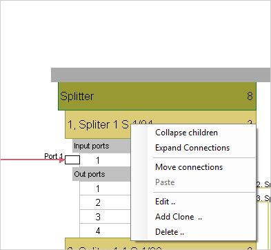
...right
click on a Device:
- Collapse children
Collapses selected element so that all of his sub-elements
are no longer visible.
- Expand connections
Expands selected element so that his sub-elements become visible.
Expansion reaches last element in the hierarchy (i.e. connector)
but only for the elements with occupied connectors. If none
of the element's connectors are occupied the element won't
be expanded.
- Move connections
Transfers connections from one device to another (see
more).
- Paste
Works in conjunction with Move connections
command (see
more).
- Edit
Opens a new window where we can edit selected element's structure
and its basic data (e.g. name). More details can be found
at Organize FDB structure
page.
- Add clone
Creates a new element based on the selected one.
- Delete
Deletes selected element together with all its sub-elements.
Program won't allow deletion if just one element's connector
is occupied (all must be free).
|
|
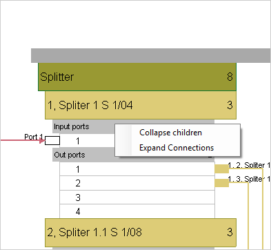
...right
click on a Input ports bar
- Collapse children
Collapses selected connectors (in or out).
- Expand connections
Expands selected connectors.
|
|
...right
click on a Out ports bar:
- Create patch (Napravi peč kabl)
Creates a new patch cable.
A cable can be created to the left and to the right of a device.
Cables to the right are used to connect devices between themselves
while cables on the left are for making connections between
devices and patch panel of the FDO or with splice box.
|
|
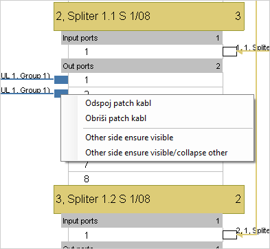
...right
click on a Patch cable connector:
- Odspoji peč kabl
Disconnects patch cable from the connector.
- Obriši peč kabl
Deletes the patch cable from the FDB.
- Other side ensure visible
Expands collapsed elements to which other end of the patch
cable is connected so that the entire connection is visible.
- Other side ensure visible / collapse
other
Expands collapsed elements to which other end of the patch
cable is connected while collapsing all other elements so
that the entire connection is visible and visually isolated
from other connections.
|
|
|