Fiber splicing [FDB]
FDB fiber splicing procedure
Fiber splicing/connecting within FDB is performed in the Device box window which can be opened in two ways: |
|
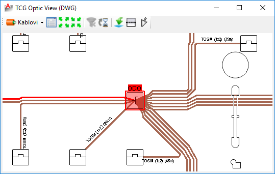
First method (recommended): Double-click on a FDB symbol while you are on a schematic display i.e. on a TCG Optic View window (figure 1) which is opened by the FO schema command. |
Second method: |
Slika 1 |
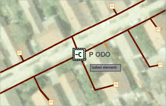
Slika 2 |
So, in both cases Device box window is opened.
We recommend that you first learn about
this window because in order to be able to successfully perform fiber
splicing/connecting it is necessary to be acquainted with its elements,
ways you can use them and commands that are offered (many are on the context
menus that are opened on a right-click).
| Note: |
To navigate in Device box window use mouse wheel. |
Fiber splicing/connecting
Fiber splicing is made by dragging an element of the infrastructure to connectors of a patch panel or to the splice points of a splice box.
There are three ways to splice fibers using the drag and drop technique:
- By dragging a fiber
Select one or more fibers and drag it to desired connector or splice point (if it is splicing in a splice box).
Pay attention that, unlike splicing within a ODF, it is now possible to select more fibers at once.
This can be done by holding SHIFT key while clicking on a fibers or by using window selection technique.
- By dragging a buffer tube
Select one buffer tube and drag it to desired connector or splice point (if it is splicing in a splice box).
In this case all fibers of the buffer tube shall be connected i.e. all its remaining fibers if some of its fibers are already connected.
Ports or splice points are going to be occupied (on a mouse release) from the topmost pointed element downwards. Number of taken ports will correspond to the number of carried fibers.
Also worth knowing is that if there is not enough ports to accept all fibers program will refuse to complete the operation. - By dragging an entire cable
Everything is the same as with buffer tube only this time all buffer tubes (i.e. all fibers) of the cable are included in the process.
| Note: |
By dragging a buffer tube or cable only remaining fibers
shall be connected/spliced. |
Disconnecting fibers
To disconnect fibers - select fibers on occupied connectors and drag
them back to cable of their origin (cable's white field to be exact).
It is possible to disconnect fibers of only one cable at once.
More fibers can be selected by holding pressed SHIFT key while clicking
on individual fibers or by using window select technique. Keep in mind
that selected fibers must belong to a single cable.
While disconnecting we can use additional tools that will make the operation easier:
- By clicking on a connected fiber and than calling the Expand
fiber tube exclusive command (from the context menu opened
by a right-click) we can easily find fiber's buffer tube and consequently
its cable.
Once we've done this it is easy to select remaining fibers of the buffer tube or the cable.
We do this using the command:
- Select connected fibers, wether by
right-clicking on a cable or on a buffer tube.
Do this on the left side of the window where available OSP cables are displayed.
Adding a patch cable
Patch cable can be added while we are in the Device box window.
Patch cables can be added within a FDB on two locations:
- To the left of the devices area i.e. between devices area and patch
panel area.
These patch cables are commonly used to connect devices with patch panel or splice box.
- To the right of the devices area.
These patch cables are used to connect devices between themselves.
Note: There is no difference in the real world between the two. Distinction is made purely to have neatly arranged patch cables.
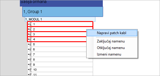
To create a patch cable:
Select one connector on a device (left-click) or more of them (use SHIFT)
if you want to create several patch cables at once.
Connector is now marked with red rectangle. Right click on selected ports
opens context menu.
From the context menu select either <-Create Patch
(Left) or Create Patch (Right) ->
(figure 6).
Procedure is the same if you want to create a patch cable on a patch panel
connectors except tis time only one command shall be offered - Create
patch.
Creating patch cable using Create Patch command. |
Creating patch cable using <-Create Patch (Left) command. |
Creating patch cable using Create Patch (Right)-> command. |
|
|
|
A
patch cable is created between patch panel and devices. |
A patch cable is created to
the right of devices. |
|
|
|
|
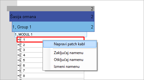
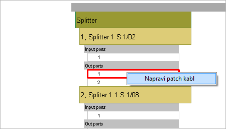
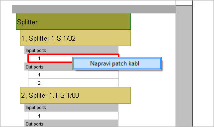
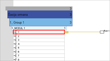
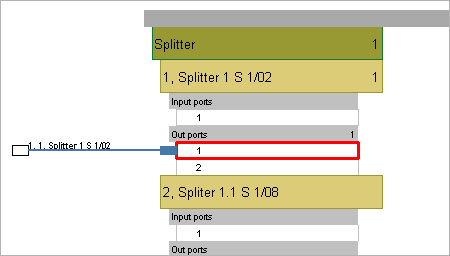
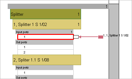
Figure 6
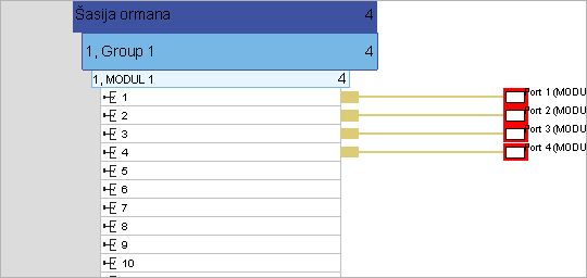
Newly created cable is, on one end, connected to a connector at which
it was created while its other end is free.
Both ends are represented with a rectangle. Label near it displays numeration
of a connector on the opposite side.
Patch cable ends (rectangles) can be moved. We move the free patch cable
end (drag and drop) to a desired connector and thus make connection.
Additionally, cable can be moved to any other location to connect some different connectors.
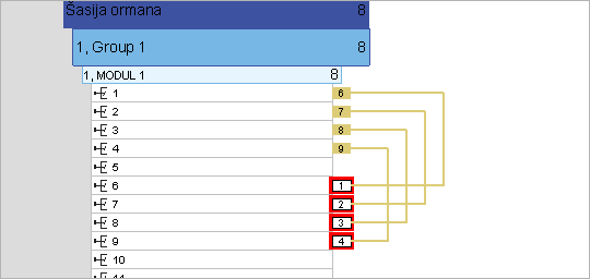
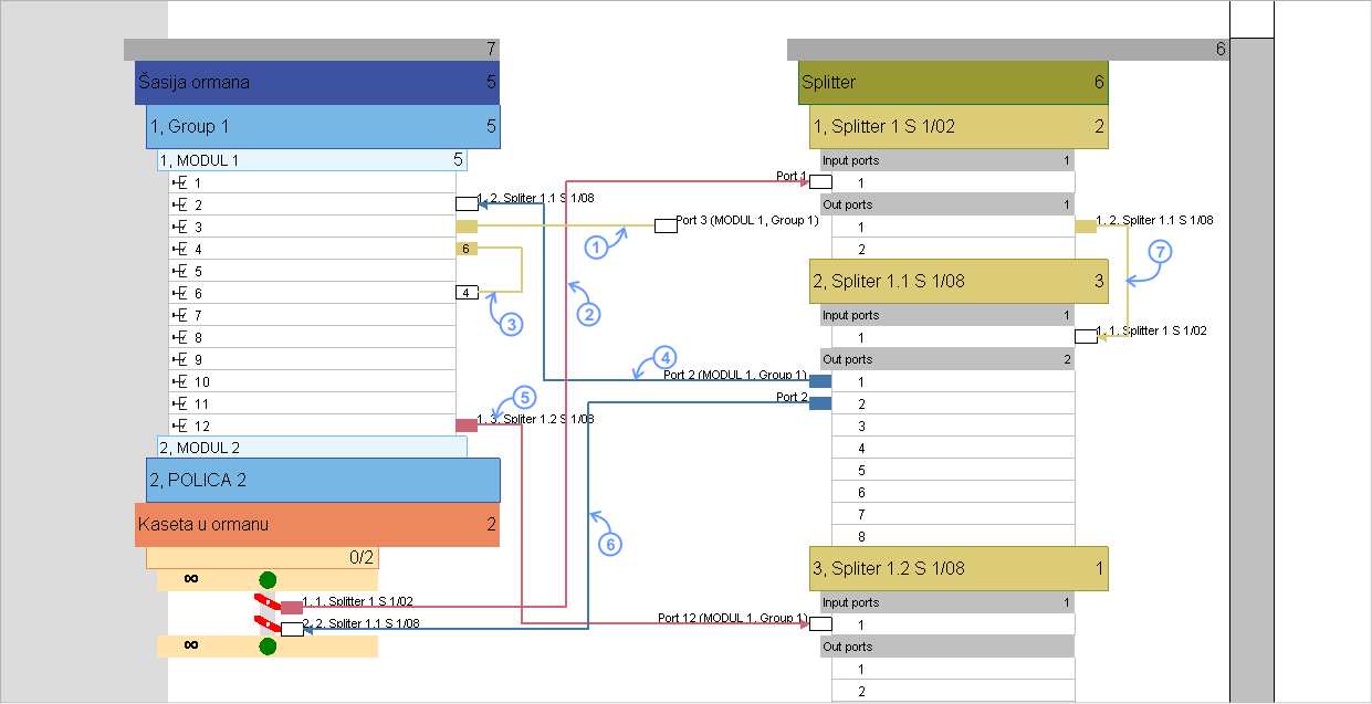
Image below shows patch cables generated in various ways and different connections made by them (marked from 1 to 7):
- Newly created patch cable. Cable is connected to the connector used to create it while the other end is free and awaits to be connected.
- Patch cable that connects a fiber of a OSP cable terminated in a splice box with an incoming port of a splitter (image still does not show OSP cable fiber).
- Patch cable that interconnects connectors of a single module on a patch panel.
- Patch cable that connects outgoing port of a splitter (of second order) to a patch panel connector.
- Patch cable that connects patch cable connector to an incoming port of a splitter.
- Patch cable that connects outgoing splitter port to a OSP cable's fiber terminated in a splice box.
- Patch cable that interconnects devices.
Slika 7
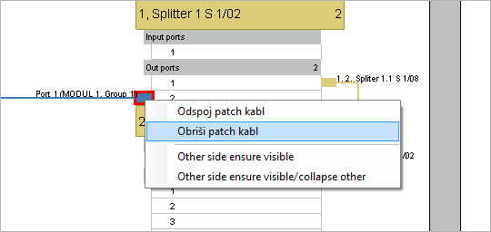
Delete patch cable
To delete a patch cable, select the rectangle on the end of it, right-click to open context menu and run Delete patch cord command.
Disconnect patch cable
To disconnect a patch cable, select the rectangle on the end of it, right-click to open context menu and call Unplug patch cord command.
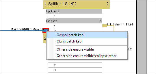
After that, the patch cable is displayed as seen on an image below (left
patch cable).
We can now connect it on a connector of our will.
Create a group of patch cables
Use a window select technique to select multiple connectors that you want to connect (figure 9). Multiple connectors can also be selected if we press and hold SHIFT key while left-clicking on connectors. Now, use right-click on selected connectors to open context menu. From the menu call Create patch command (figure 10).
|
Figure 9 |
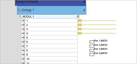
A group of patch cables has been created and initially are connected to previously selected connectors. Free ends need to be placed on ports that we want to connect to (figure 11).
|
Figure 10 |
Free ends can be moved one by one or we can select more of them (or all of them for that matter) and than move them to desired connectors. Image shows the patch cable ends as they are shown during the movement (figure 12). |
Figure 12 |
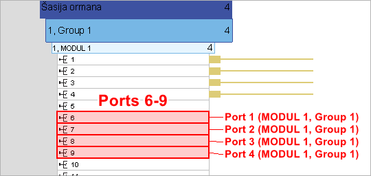
While we move the mouse across the connectors, program marks them (red) to indicate which ones would be occupied. At the same time names of connectors at the other end are displayed next to marked connectors (figure 13). |
Figure 13 |
Connections are made by releasing
the mouse This completes the process.
|
Figure 14 |
|
|