Command: Export to block
Export to block (![]() ) command
opens TCG Block Manager window, used
for creating blocks.
) command
opens TCG Block Manager window, used
for creating blocks.
These blocks contain vector graphics that can later be inserted into the
layouts and printed (see Create Appendix
command).
Export to block (![]() )
command can be found on the toolbars of the following windows:
)
command can be found on the toolbars of the following windows:
- FO Schematic Diagram
- Fiber Splicing - Distribution Frame
- Fiber Splicing - Splice Point
- Edit ISP (Inside plant)
- Schematic Display of Duct Bank
The entire workspace content in the moment
of running Export to block (![]() ) command will be exported
to the block.
) command will be exported
to the block.
E.g. If we are in “Fiber” mode in the schematic diagram and we’ve shown the fibers in circuit names’ colors, while the fibers are grouped unlimitedly, then a block displaying exactly that will be created, just the way it appears in the schematic diagram window (think of it as a print screen where even invisible parts of workspace are captured and the result is a vector graphic rather than raster).
Procedure
| Note: |
The further text describes the procedure of exporting fiber plan
to block, in order to prepare it for printing. |
First, prepare everything in the FO Schematic Diagram window, so as to get the desired display (Figure 1).
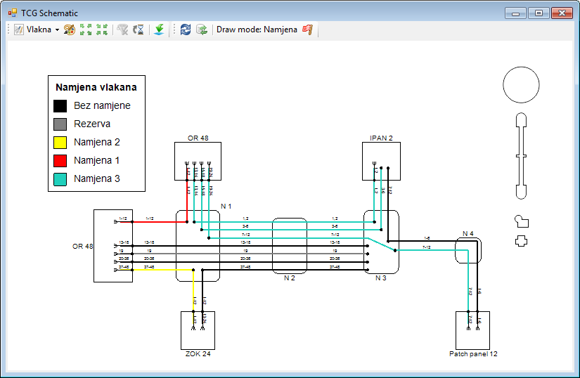
Figure 1
In the example we’ve chosen the mode “Fibers", we’ve set the fibers’ display so that they are in circuit names’ colors and we’ve grouped fibers unlimitedly.
In addition, from the Floating Pane window
(Legend tab) we’ve taken the fiber circuit
name legend and inserted it next to the schematic diagram (Figure 2).
(Legend window is opened by clicking on Display Floating Pane icon ( )
located at the toolbar of the FO Schematic Diagram window.)
)
located at the toolbar of the FO Schematic Diagram window.)
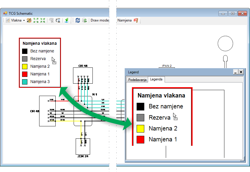
Figure 2
Now that everything is prepared, run Export to
block (![]() ) command
from FO Schematic Diagram window
toolbar.
) command
from FO Schematic Diagram window
toolbar.
TCG Block Manager window opens (Figure
3).
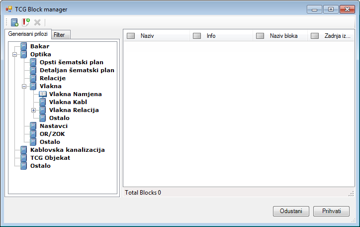
Figure 3
Click on New Block (  )
icon to open the window (Figure 4) in which we assign the block name in
the „Label” field.
)
icon to open the window (Figure 4) in which we assign the block name in
the „Label” field.
Based on the block name, the program automatically generates the "Block
Name" (since the name needs to comply with certain rules).
Finally, the user adds a brief description of the block (optional).
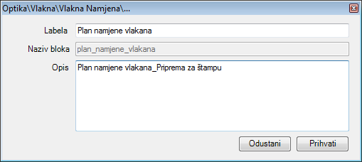
Figure 4
By clicking Accept a new block is created,
which is then stored in the appropriate directory (Figure 5).
Block content is everything that you saw in the FO
Schematic Diagram window (Figure 1).
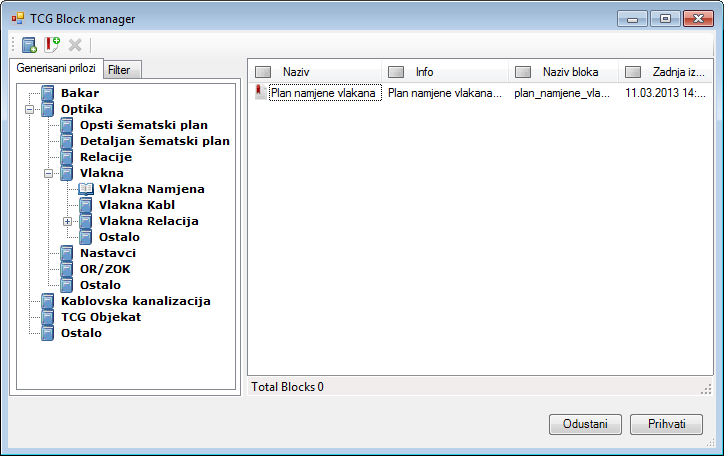
Figure 5
A block gets created by clicking Accept button, and the program displays window (Figure 6) to inform you that the task is successfully completed.
Figure 6
Now that the block is created, we can insert it to into the layout or the site plan drawing, as described on Create Appendix page.