Fiber Splicing [Splice Point] - Procedure
Procedure of fiber splicing in splice point
Procedure of fiber splicing in splice point is done in Fiber Splicing [Splice Point] window which is reached in one of two ways: |
|
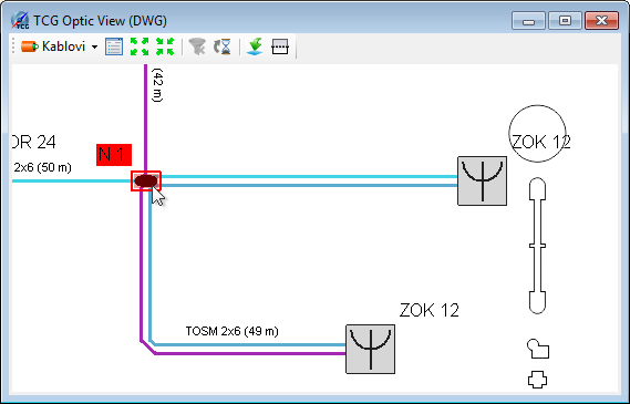
Method 1 (recommended) Double-clicking on the splice point symbol while in the schematic
diagram (i.e. TCG
Optic View window opened by FO Schema
command) |
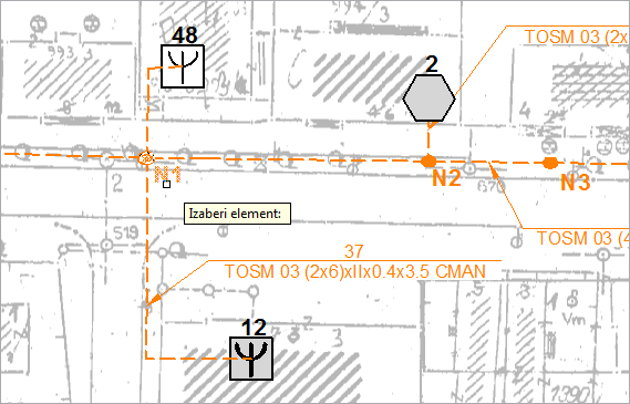
Method 2 From the main menu run Fiber Optics
> Fiber Splicing |
Figure 1 |
Figure 2 |
In both cases Fiber Splicing [Splice Point] window opens.
It is recommended to study this window before proceeding with the splicing, for you must get acquainted with the elements of this window, method of operation with them and commands offered (many are available by right-clicking on the element which is the subject of operation) to perform splicing successfully.
| Note: |
We navigate in Fiber Splicing [Splice
Point] window by rolling the mouse wheel (zoom +/-) and
pressing the mouse wheel (pan). |
Fiber Splicing
Fiber splicing starts in Fiber Splicing [Splice
Point] window by selecting two fiber groups whose fibers we would
like to splice.
The procedure is as follows:
One fiber group is selected by left-clicking,
and then the second fiber group is selected by left-clicking while holding
pressed SHIFT key on the keyboard.
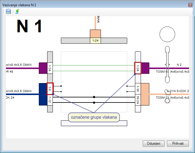
Figure 5
When we have clicked on the second fiber group, Splicing in Splice Point
window automatically opens (Figure 6).
Fiber group which has first been selected will be on the left, and the
second one on the right.
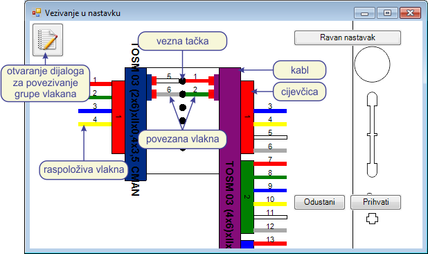
Figure 6
Procedure of fiber splicing (in Splicing in Splice Point window)
Fiber splicing is done by dragging and dropping infrastructure elements onto splice dots (fiber, buffer tube and cable are movable elements).
Number of splice dots is determined in relation to the cable with less
available fibers.
(Bear in mind that sometimes not all the cable fibers are shown but only
those fibers from groups selected in the previous step.)
There are three ways to perform splicing by dragging and dropping:
- Splicing single fiber
select one fiber and drag and drop it onto the desired splice dot.
Drag and drop the fiber of the other cable which is to be spliced with the previous fiber in the same manner. - Drag and drop buffer tube
select one buffer tube and drag and drop it onto the desired splice dot. In this case, splicing of all fibers of the buffer tube will be performed. Splice dots will be filled starting from the splice dot shown by the mouse during the release of the buffer tube filling the required number of splice dots. If the number of available buffer tube fibers exceeds the number of available splice dots, the program will refuse to perform the splicing. - Drag and drop cable
everything is the same as dragging and dropping of buffer tubes, but this time all the cable fibers will be spliced.
| Note: |
By dragging and dropping buffer tube or cable, only splicing of the available fibers will be made, which means that this dragging and dropping will not disturb the order of previously spliced fibers of that same cable/buffer tube. |
Command: Straight-through Splice
Fibers in the splice point can be spliced by clicking Straight-through Splice button. In this case, all the available fibers will be spliced in the order of their arrangement in the buffer tubes (one on one). Number of splices is determined in relation to the cable with less available fibers.
Fiber splicing
(in: Fiber Splicing
window)
Click on the  icon to
open Connect window (image below).
icon to
open Connect window (image below).
Same kind of window is used for splicing when we splice directly on
a schematic diagram. Given that the procedure
is already described in details it shall not be repeated here.
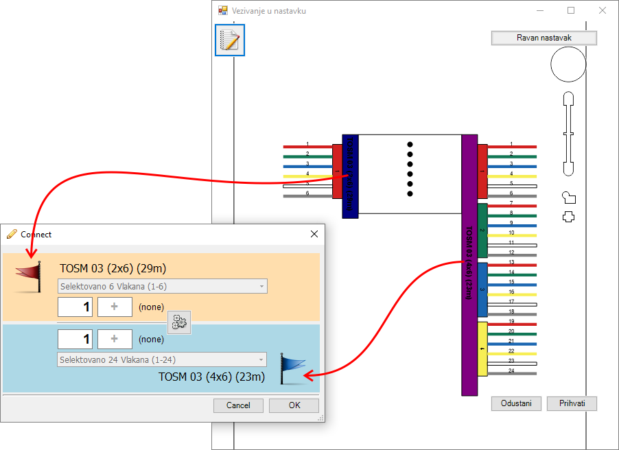
However it should be noted that the left cable of the Vezivanje
u nastavku window corresponds to the upper cable of the Connect
window (red flag) while
the right cable of the Vezivanje u nastavku
window corresponds to the lower cable of the Connect
window (blue flag).
In short, we fill the fields with a range of fibers of both cables that
need to be connected (image below).
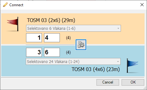
In the end - click the OK button.
Fiber unsplicing
Fiber unsplicing can be done in three ways:
- Unsplicing single fiber
this method is used when we want to unsplice an individual fiber. Unsplicing is done by dragging and dropping the fiber from the splice dot to the proper cable. - Unsplice all fiber of buffer tube
this method is used when all the fibers of one buffer tube should be unspliced. The context menu is opened by right-clicking the buffer tube symbol. By selecting menu command: Disconnect All Fibers of This Buffer tube disconnect the fibers. After this procedure the fibers are shown as available fibers on the proper buffer tube. - Unsplice all fiber of cable
this method is used when all the fibers of one cable should be unspliced. The menu is opened by right-clicking the cable. By selecting menu command: Disconnect All Fibers of This Buffer tube disconnect the fibers. After this procedure the fibers are shown as available fibers on the proper buffer tubes of the observed cable.