Patch panel
| Command: | Patch panel |
| Menu path: | Fiber Optics > FO devices > Patch panel |
| Icon: | 
 |
| Functional description: | Patch panel placement on the site plan. |
Patch Panel command places patch panels with
predefined properties.
Patch panel symbol is displayed on the site plan drawing as shown in Figure
1.
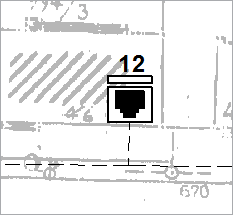
Figure 1
This method results in patch panel with the following properties:
Patch panel properties
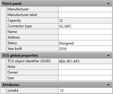
Use Properties window to set the patch panel properties (Figure 2).
| Warning: |
Even though Attributes > Label
field is enabled, new value entry will not bring about actual
property change. |
Patch panel placement
The placement procedure is the same for all FO nodal elements.
The difference lies in the object which is to be placed by the used command
(ODF, OTB, Patch Panel, Device, Router, IPAN or ONT).
The laying procedure is described on Laying
FO nodal elements page.
Splicing
The procedure of patch panel splicing/connecting is described on Fiber splicing in FDB page.