Placing FO nodal element
Placement of FO nodal element is a procedure by which the spatial position
of FO nodal element is defined in the site plan drawing.
There are no preconditions for placing a FO nodal element.
In other words, FO nodal elements symbol can also be placed into a completely
empty drawing.
FO nodal elements are placed by running one of the following commands:
| Note: |
The laying procedure is also the same for the following nodal elements of fiber optics: |
Procedure
| Note: |
ODF placement is
described further on. The placement procedure is the same for
all the above commands. |
From the main menu run Fiber Optics > FO Devices > ODF command.
The cursor is displayed in a form of plus sign ("+") with a message* next to it instructing us to show the location or manually enter the coordinates where we want to place the ODF (Figure 1).
Select soute-point.
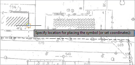
Figure 1
Clicking on the desired location generates ODF symbol (Figure 2).
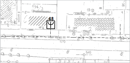
Figure 2
We can edit the properties of a newly added symbol via Properties window.
Select ODF symbol (Figure 3).
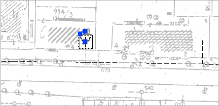
Figure 3
In Properties window set the ODF properties (Figure 4).
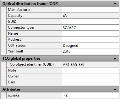
Figure 4