Adding cables to FO paths
(using the schematic display)
This page describes adding cables to FO paths using the schematic diagram.
This is one of the three ways in which this can be done, but is probably
the most intuitive one.
In this way you can add cables in already existing FO paths, but you can’t
define new FO paths (this is done in FO Paths
window opened with Fiber Optics > FO Paths
command).
Working with FO paths is described in FO Paths
window.
Procedure: Adding cables to FO paths
To be able to work with FO Paths in the schematic diagram, we need to be in the “FO Paths” mode (Toolbar > Drop-down menu > FO Paths) (Figure 1).

Figure 1
Cables are added to FO Paths by first selecting the cables you want
to add to a FO path
(select them using selection rectangle i.e. by dragging the mouse or by
using the SHIFT key and selecting multiple cables).
Selected cables are marked with bold red line (Figure 2).
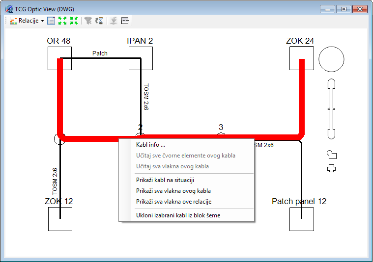
Figure 2
Right-click on the cable (or multiple selected cables), and then select
Cable Info command from the drop down list
(Figure 2).
Cable Info window opens (Figure 3).
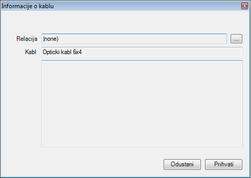
Figure 3
In the Cable Info window click (  ) button.
FO Paths window opens (Figure 4).
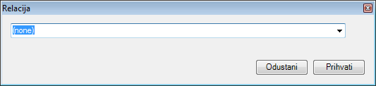
Figure 4
FO Paths window contains a drop-down list
from which we select the predefined FO paths (FO paths are in the codebook).
The method is as follows:
First, type a part of the FO path name (already existing in the codebook)
in the drop-down list field.
As you enter text, the drop-down list is automatically filled with all
the FO paths that contain the entered text (Figure 5).
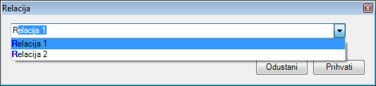
Figure 5
Left-click to select the desired FO path.
FO path is selected (Figure 6).
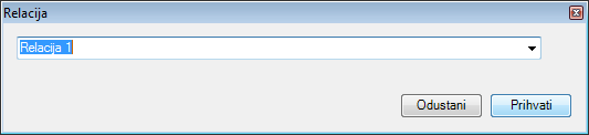
Figure 6
Click on the Accept button to accept the selected FO path.
| Note: |
If the needed FO path doesn’t exist in the codebook, we can create it in FO Paths window which we open with Optical Network > FO Paths command (described on FO Paths page). |
FO Paths window closes and we are once again
in the Cable Info window.
Text field “FO Paths" now displays the name of the selected FO path
(Figure 7).
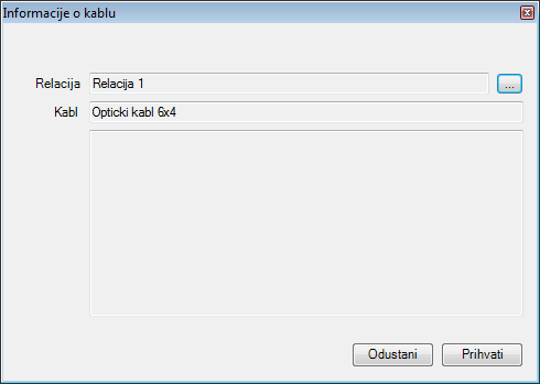
Figure 7
By clicking Accept complete the process of assigning cables to FO paths. Repeat the procedure for cables of other FO paths.
In the schematic diagram, added cables are displayed in colors of FO paths to which they belong (Figure 8).
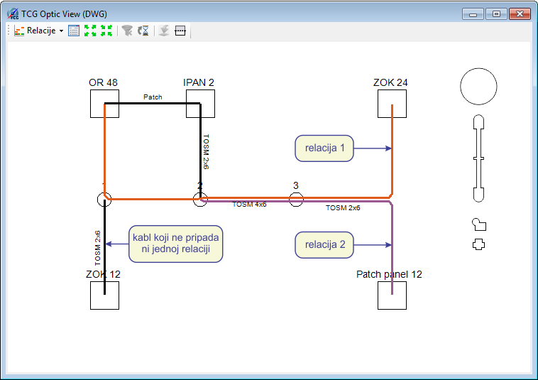
Figure 8