Fiber Trace (Map)
| Introductory note: |
Finding path (fiber trace) can be done in three different places:
( * In case of work with the "Fiber Trace” tool on "TCG Map-Optics (GIS Database)", these two approaches can complement each other.) The "Fiber Trace" tag itself slightly varies in these three cases. In further text we described the work of TCG Map Optics (GIS Database) i.e. highlighted the differences and additional explanations of "Fiber Trace" tool when used on the map. |
Fiber trace tool enables finding the optimal path between two or more nodal elements of FO network. The path is searched for at the level of the fiber.
We say that the path is optimal because the program searches for the shortest path, respecting criteria assigned by the user.
Tools used for finding the optimal path are in the Fiber Trace (Map) tag. To reach Fiber Trace tag, we have to open TCG Map - Optics tool, and then run Additional Tools ( ) command which opens the side palette (docker) at which the tag is located.
Tag: Fiber Trace
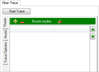
Figure 1
The process of finding the optimal path between two or more nodal elements of FO network (fiber trace), which refers to the map search, differs from (fiber trace) search in the schematic display in the following:
- The search includes all infrastructure elements in GIS Database,
respecting the criteria set by the user, meaning - that the search can be additionally limited exclusively to elements on the screen (i.e. visible part of the map window).
- Cables can be added to the "Avoid" list (which is not the case with the schemes).
- Tag’s main menu does NOT have the following buttons: Filter, OTDR and Delete.
- Elements can be added to the "Route" and "Avoid" list directly from the map (right-click).
Everything else is the same, so make sure you study Fiber Trace tag described on Fiber Trace (scheme) page - (The differences are explained at the end of that as well as this page).
Procedure
The process is also almost exactly the same as the process of finding the optimal path to the scheme.
The only difference in the procedure is that the elements between which the path is sought (i.e. Fiber(s)) are added to the "Route" or "Avoid" list by selecting these elements directly on the map, and then inserting them in the list in one of the two modes described (described on Fiber Trace (scheme)).
There is a conceptual difference in the way we reach the optimal path when in the TCG Site-Optics tool.
There are two options:
If the search is performed over the data from the GIS Database, this can be done using the Additional Tools () > Fiber Trace (map) tool. The final result of this search is an automatically generated scheme of the proposed path (future fiber(s)). The search is performed over the entire database or over the elements shown in the visible part of the map window (depending on the user's demand).
Another case is when the user pre-arranges the schematic display, i.e. extracts a certain part of the network from the GIS database, and then performs the search using “Fiber Trace” (in the scheme). In this way, the user limits the search to one part of the network, i.e. certain elements (those in the scheme).
| Note: |
When the search is performed in the scheme, the user can further filter the fibers. E.g. only fibers with the circuit name "Reserve” can be displayed. In this case the program searches for the optimal path only through fibers with circuit name “Reserve” (otherwise fibers without circuit name would be used if we would e.g. select option “Free” in the Fiber Trace > Trace Options tab). Simply said - what you see in the scheme is what is included in the search for the optimal path. |
Comparison of “Fiber Trace” tool:
The tool is located at:
|
TCG Map-Optics (GIS DB) |
TCG Map-Optics (GIS DB) |
TeleCAD-GIS (DWG) |
The search includes:
|
All elements from the GIS database or all elements from GIS database currently visible on the screen (depending on the users' preference) |
Only elements visible in the scheme. The scheme itself is generated based on the infrastructure in GIS database. |
Only elements visible in the scheme. The scheme itself is generated based on the infrastructure in the *.dwg drawing. |
Avoiding nodal elements. |
It is possible |
It is possible |
It is possible |
Avoiding cables. |
It is possible |
It is not possible |
It is not possible |
Alternative for avoiding cables. |
Unnecessary |
Unnecessary - if the scheme is generated based on the map search (Fiber Trace). In other cases - by removing cables from the scheme. |
Removing cables from the scheme |
Filtering search results |
Not possible directly on the map (there is no Filter button) but you can do it indirectly in the scheme by filtering the search results. |
Enabled (Filter button) |
Enabled (Filter button) |
Analysis of attenuation and Power Budget over the proposed fiber. |
Not possible directly on the map (there is no OTDR button) but you can do it possible indirectly in the scheme. |
Enabled (OTDR button) |
Enabled (OTDR button) |
Conclusion: |
These two approaches complement each other, so practically all tasks can be done by combining them. |
|
|
The essential difference between the "Fiber Trace" tool within TeleCAD-GIS and TCG Map-Optics is in the elements involved in the search.
|
|||