Fiber trace (scheme)
| Introductory note: |
Finding path (fiber trace) can be done in three different
places:
(* In case of work with the "Fiber Trace”
tool on "TCG Map-Optics (GIS Database)," these two approaches
can complement each other.)
The "Fiber Trace" tag itself slightly varies in these
three cases.
All three variants of the tag, as well as the additional commands
of "Fiber Trace" tool are described in parallel on this
page. So, first read this page.
In addition, the method of "Fiber Trace" tool’s work,
when used within the TCG Map-Optics
(GIS database) tool, is described on Fiber
Trace (map) page. To avoid repetition, on that page we only
highlighted the differences and gave additional explanations of
"Fiber Trace" tool when used on the map. |
Fiber trace tool enables finding the optimal path between two or more nodal
elements of FO network. The path is found at the level of the fiber.
We say that the path is optimal because the program searches for the shortest
path respecting the criteria assigned by the user.
Tools used for finding the optimal path are in the Fiber
Trace tag. In order to reach the Fiber Tracetag,
we have to open the fiber scheme and move to “Fibers” mode. Fiber
Trace tag is located in the Legend,
which, if not open, we open with Legend ( )
command located on the main menu of the fiber scheme. )
command located on the main menu of the fiber scheme.
Tag: Fiber Trace
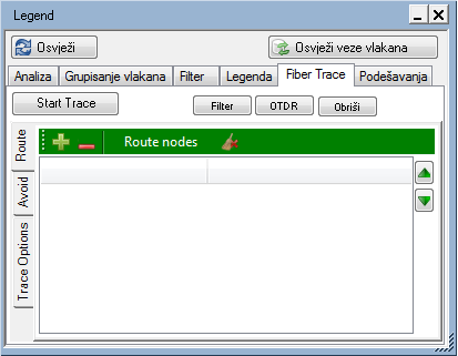
Figure 1
Fiber Trace tag has:
- main menu (with four commands in the scheme, or a single command
on the map)
and is further divided into three more tags (set aside):
- Route
- Avoid
- Trace Options (criteria of path searching)
Main menu
Main menu contains the following items:
- Start trace
Finds the path along the fiber, based on the defined criteria.
- Filter
Separates the fibers (obtained as search result) in the scheme .
Tip: After the first click, a group of fibers will often be separated
so you need to click once more to get to the individual fiber.
Note: Doesn't exist in Fiber Trace (map)
tag.)
- OTDR
Opens OTDR Trace tool, primarily in order
to overview the Optical Power Budget
for the proposed path’s fiber.
(More on attenuation calculation and Optical
Power Budget can be seen on their
respective pages.)
(Note: Doesn't exist in Fiber Trace (map)
tag.)
- Delete
Deletes the search settings as well as the auxiliary graphic elements
generated on that occasion
(Note: Doesn't exist in Fiber Trace tag
(map).)
Side tags:
Route
|
Side tag „Route”
enables:
 - Adding nodal elements between
which we’re searching for the path - Adding nodal elements between
which we’re searching for the path
(two or more nodal elements can be added to the list).
 - Removes selected elements from
the list - Removes selected elements from
the list
(you can select multiple list items at once using the SHIFT
or CTRL key, in the standard Windows way).
  -
Change the order of nodal elements in the list -
Change the order of nodal elements in the list
(this has a direct impact on the final path search result.)
- Show (right click on a list
item) - Locating elements in the scheme/map
(depending on whether the command was run from Fiber
Trace tag in the scheme or on the map).
Note:
Nodal element can also be added to this list by right-clicking
on it and running command from the context menu: Route
Trace > Add to Route. In this way, elements are added
one by one, but not multiple elements at once.
Removal from the list is done using Route
Trace > Remove node command, in „Route” or „Avoid” list.
All elements can be removed at once using Clear
all command ( ). ). |
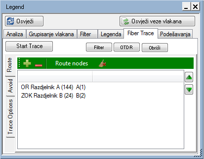
Figure 2 (scheme)
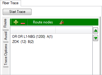
Figure 2a (map) |
Avoid
|
Side tag „Avoid”
enables:
- - Adding elements to the list which
you wish to avoid when searching for the path (when working
with the scheme, you can add only nodal elements to the list,
not the cables, but there is another way to exclude the cables
from the search*)
- - Remove selected elements from
the list
(you can select multiple list items at once using the SHIFT
or CTRL key, in the standard Windows way).
- Show (right click on a list
item) - Locating elements in the scheme/map
(depending on whether the command was run from Fiber
Trace tag in the scheme or on the map).
Note:
Nodal element can also be added to this list or avoided by right-clicking
on it and running command from the context menu:Route
Trace > Add to Route. In this way, elements are added
one by one, but not multiple elements at once.
Removal from the list is done using Route
Trace > Remove node command, in „Route” or „Avoid” list.
All elements can be removed at once using Clear
all command ().
Tip:
Avoid tag can be used to e.g. simulate
the break point.
You can also use it to avoid the path that the program offers,
for any reason.
*Clarification:
Any element, including cables, can be removed from the scheme.
Given that search for optimal path is done only through the objects
in the scheme, we can achieve the same goal as when adding cable
to Avoid list.
(To remove the cable from the scheme, highlight it, then right
click on it to open the context menu from which you then run Remove selected cables from the block scheme.) |
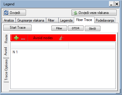
Figure 3 (scheme)
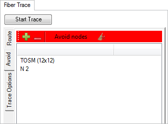
Figure 3a (map) |
Trace Options
|
Side tag Trace
Options enables you to define criteria for the search.
The criteria vary depending on the user needs i.e. reasons for
seeking the path between the nodal elements (ultimate goal of
the user).
The options are:
- All/Free
The program will include all fibers or only free fibers in
the search.
Free fibers are those that have no defined circuit name or
in the “Circuit Name" field have displayed: “Splice point".
- Trace
in Viewport
Limits the search to the elements currently visible in the
map window i.e. doesn’t search the whole GIS database.
(Note: This option is only available in Fiber
Trace (map).)
- Fiber
selection field
In this field, the user defines how many fibers (along the
same path) should be found.
- Minimal
Actions/Minimal Attenuation
The user determines whether the offered fiber (i.e. search
result) will need as few as possible interventions (connection,
crossing etc.) to be accomplished or the attenuation along
it will be reduced to minimum.
- Checkboxes:
- Add
Patch
“Adds” patch cable to the distribution frame to enable
the connection between the assigned nodal elements. Practically,
a new fiber is proposed, created as a result of connecting
the existing ones. Also, a cable will be "added”
between the two distribution frames if they are at the
same point or in the same TCG building.
- Add
Splice
“Splices” the fibers in the splice point to enable the
connection between the assigned nodal elements. Practically,
a new fiber is proposed, created as a result of connecting
the existing ones. Also, fibers will be “spliced"
even if they are terminated in two different splice points,
provided that both are located at the same point.
- Cut
Patch
Breaks the existing fibers in the points where they are
connected by patch cables, in order to use some newly-created
fibers for the connection between the assigned nodal elements.
It is assumed that the newly-created fiber will be subsequently
connected with a fiber terminating in the DF, whether
terminating at connectors or splice boxes.
- Cut
Splice
Breaks the existing fibers spliced in the splice points,
in order to use some newly-created fibers for the connection
between the assigned nodal elements. It is assumed that
some of the newly-created fibers will be subsequently
connected with a fiber terminating in the splice point.
Note:
If none of the options is selected, the program will try to
find only those paths which provide direct connection between
the nodal elements (i.e. the existing fiber that connects
them).
- The importance
of fiber occupation
This is where the user defines how important is it for the
search result not to occupy the “Last free fibers” along the
proposed path.
"The importance of fiber
occupation" option will be explained in more detail.
In finding the path (fiber/ fibers) between two or more nodal
elements of the network, the program will strive to provide the
most optimal solution in accordance with the set criteria.
This can be a path achieved with minimum intervention or the
path which is the shortest and thus has minimal attenuation. This
solution leads to the path that can close some corridors by using
the last available fibers at certain network segments (corridors).
Another approach would be that the proposed path tends to use
"more passable corridors" (those with more available
fibers), still seeking the optimal path.
"The importance of fiber occupation" option is literally
a balance of the scale that decides whether the proposed solution
will incline towards one or the other approach, the options being:
- Irrelevant
(slider on the left)
The program searches for the optimum path with no regard to
how the proposed path will affect the passability of existing
corridors
- Medium
relevance and Highly
relevant (slider in the middle or to the right)
The program searches for the optimum path with no regard to
how the proposed path will affect the passability of existing
corridors. Selecting the levels of importance, the user gets
different solutions and chooses one of them.
Note:
The mechanism based on which the program evaluates and compares
the possible solutions is too complex to explain here. The user
should experiment on his/her own in order to gain insight into
possible solutions. |
Figure 4 (scheme)
Figure 4a (map) |
After assigning the criteria (or accepting the default ones), the user
can start searching for an optimal path between the nodal elements of
FO network.
Procedure
The procedure begins by assigning search criteria in Fiber
Trace > Trace Options tag (depending
on the desired objective).
(You can also be satisfied with the default criteria. In this case, this
step is unnecessary.)
Then, determine the nodal elements
between which you seek path through the fibers.
Do this by selecting the nodal elements in the scheme and then
adding them to “Route” list, whether using icon () in Fiber Trace
> Route tag or right-clicking on
the nodal element and running Route Trace
> Add to Route command from the context menu.
In addition, you can order the program to avoid certain elements
when seeking paths.
Do this by selecting the nodal elements in the scheme and then
adding them to “Avoid” list, whether using icon () in Fiber Trace
> Avoid tag or right-clicking on
the nodal element and running Route Trace
> Avoid node command from the context menu. |

|
Nodal elements between which we seek path. |

|
Nodal elements to avoid. |

|
Cables to avoid. |
|
| Addition: |
In case the search is performed on the map, select the nodal
elements (between which you’re seeking path or those you’re avoiding)
on the map, and then add them to the "Route" or "Avoid”
list in exactly the same way as in the scheme. |
Map layout of elements included
in the path search. (Figure 5)
|
Nodal elements between which we seek path. |
|
Nodal elements to avoid. (not present in the figure) |
|
Cables to avoid. |
|
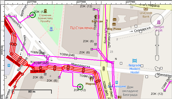
Figure 5 |
Map layout of elements included
in the path search. (Figure 6)
|
Nodal elements between which we seek path. |
|
Nodal elements to avoid. |
|
In the scheme, it’s not possible to add cables to
the list for avoidance. |
|
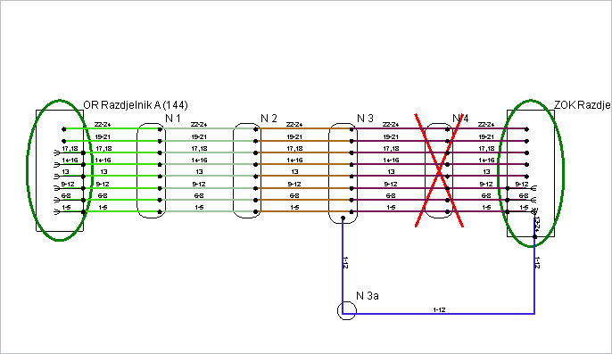
Figure 6 |
Now that everything is set up, you just need to click the Start
Trace button on the main menu.
The program will find a path between the assigned nodal elements, or
a message will pop out stating that the path is not found, if there is
no path that meets the required criteria.
| Note: |
In case the search is performed on the map,
search will be carried through all the elements in the GIS database
or only those that are in the map window (depending on the settings).
In case the search is done in the scheme,
search will be carried out through the elements that are currently
in the scheme. This means that the search will not include the
elements that are (e.g.) removed by filtration. |
Depending on the assigned criteria,
search result may be one (or more parallel):
- Fiber(s) which directly connect the assigned nodal elements
(direct connection already exists, so there’s no need for further
action).
- New fiber(s) (i.e. proposed) that would be created by merging
the existing fibers along the found path, after the user performs
actions necessary to enable the connection.
This new fiber(s) would, after the intervention, enable a direct
connection between the assigned nodal elements.
In the first case (1) fibers found in the scheme are being marked.
In the second case (2), new fiber(s) is marked in the scheme,
and nodal elements in which an action is required to create new
fiber(s) from the existing ones, are additionally marked (circled).
The actions required to create a new fiber can be: connecting
existing fibers or breaking and subsequently connecting them,
either in the splice point or in the distribution frame. |

|
Connectors in which the found fiber(s) path starts
and terminates. |

|
The proposed fiber(s), i.e. path obtained as the
search result. |

|
Logical path obtained as the search result. |

|
Element (terminal, splice point) in which an action
is required to achieve the proposed path, i.e. to create
a new fiber that meets the search criteria. |

|
Connector or splice in which an action is required
for the proposed path to be achieved, i.e. to create a
new fiber that meets the search criteria. |
|
Map layout after a path was
successfully found (Figure 5)
|
Nodal elements between which the path was
sought. |
|
Connectors in which the found fiber(s) path starts
and terminates. |
|
The proposed fiber(s), i.e. path obtained as the
search result (scheme). |
|
Logical path obtained as the search result (map). |
|
Element (terminal, splice point) in which an action
is required for the proposed path to be achieved, i.e.
to create a new fiber that meets the search criteria (map). |
|
Connector or splice in which an action is required
for the proposed path to be achieved, i.e. to create a
new fiber that meets the search criteria (scheme). |
|
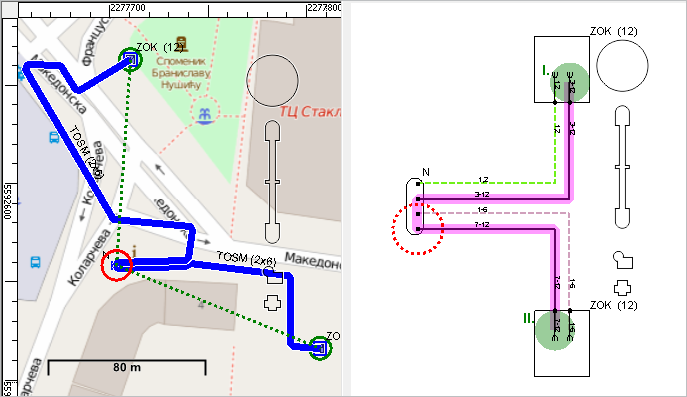
Figure 5 |
Map layout after a path was
successfully found (Figure 6)
|
Nodal elements between which the path was
sought. |
|
Connectors in which the found fiber(s) path starts
and terminates. |
|
The proposed fiber(s), i.e. path obtained as the
search result. |
|
Connector or splice in which an action is required
for the proposed path to be achieved, i.e. to create a
new fiber that meets the search criteria. |
|
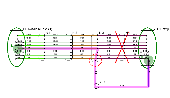
Figure 6 |
The user can modify the search criteria until finding a satisfactory
solution.
In order to evaluate the quality of the proposed solution, we can analyze
the attenuation along the FO fiber and Optical Power Budget
for the proposed fiber (by clicking onOTDR).
On that occasion the program will view the fiber as if the proposed interventions
were already made, i.e. the proposed patch cables already installed and/or
the fibers being spliced in the proposed splice points.
Note: If several parallel fibers
are offered as a search result, the program will analyze attenuation and
Power Budget only for one fiber
(first one it encounters).
Comparison of “Fiber Trace” tool
The
tool is located at:
|
TCG
Map-Optics (GIS DB)
Map |
TCG
Map-Optics (GIS DB)
Map |
TeleCAD-GIS
(DWG)
Scheme |
The
search includes:
|
All the elements
from the GIS database or all elements from GIS database currently
visible on the screen (depending on the users' preference) |
Only elements visible
in the scheme. The scheme itself is generated based on the infrastructure
in the GIS database. |
Only elements visible
in the scheme. The scheme itself is generated based on the infrastructure
in the *.dwg drawing. |
Avoiding
nodal elements.
(Adding nodal elements to the "Avoid" list.) |
It is possible |
It is possible |
It is possible |
Avoiding
cables.
(Adding cables to the "Avoid" list.) |
It is possible |
It is not possible
(there are alternatives) |
It is not possible
(there are alternatives) |
Alternative
for avoiding cables. |
Unnecessary |
Unnecessary - if
the scheme is generated based on the search (Fiber Trace) on the
map.
In other cases - by removing cables from the scheme. |
Removing cables
from the scheme |
Filtering
search results
(separation of individual fiber). |
Not possible directly
on the map (there is no Filter button)
but you can do it indirectly in the scheme by filtering the search
results. |
Enabled (Filter button) |
Enabled (Filter button) |
Analysis
of attenuation and Power Budget
over the proposed fiber. |
Not possible directly
on the map (there is no OTDR button)
but you can do it possible indirectly in the scheme. |
Enabled (OTDR button) |
Enabled (OTDR button) |
Conclusion: |
These two approaches
complement each other, so practically all tasks can be done by
combining them. |
|
The essential difference
between the "Fiber Trace" tool within TeleCAD-GIS and
TCG Map-Optics is in the elements involved in the search.
- TeleCAD-GIS - data (elements) from the site plan (DWG drawing)
- TCG Map-Optics - data (elements) from the GIS database
|
|